Radiant heat barrier insulation system

Active Publication Date: 2017-04-18
USA REPRESENTED BY THE SEC OF THE NAVY
View PDF2 Cites 5 Cited by
  • Summary
  • Abstract
  • Description
  • Claims
  • Application Information

AI Technical Summary

Benefits of technology

The present invention provides a thin insulation system that can be used in a passive way and adapted for active heating. This allows for efficient insulation in a compact design.

Problems solved by technology

However, the primary drawback of using existing passive insulation is that increased insulating properties are only achieved with increased thickness.
Unfortunately, thickness restrictions in some garments or structures can limit the effectiveness of passive insulation.

Method used


Image

  • Radiant heat barrier insulation system
  • Radiant heat barrier insulation system
  • Radiant heat barrier insulation system

Examples


Embodiment Construction

[0015]In general, the present invention is a radiant heat barrier insulation system that retains one's body heat or the heat within a structure by preventing heat loss from the body / structure. The basic principles of heat loss prevention employed by the present invention can be achieved by each of the embodiments that will be described herein. The various embodiments can be constructed to be flexible or rigid insulation systems without departing from the scope of the present invention. Accordingly, the present invention can be utilized in both garments and structures.

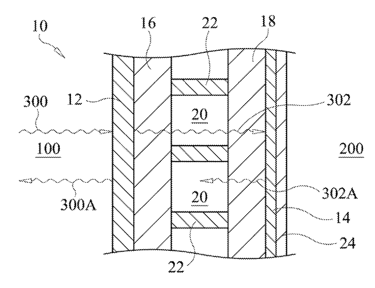
[0016]Referring now to the drawings and more particularly to FIG. 1, a cross-sectional view of a portion of a radiant heat barrier insulation system in accordance with an embodiment of the present invention is shown and is referenced generally by numeral 10. Insulation system 10 defines a radiant heat barrier that substantially prevents heat loss from a heated region 100 (e.g., a living being, a heated structure, warmer...


PUM


Abstract

A radiant heat barrier insulation system includes a first substrate with a first layer of aluminum thereon. The system also includes a second substrate with a second layer of aluminum thereon. The first substrate is positioned to oppose the second substrate such that a gap is defined between the first substrate and the second substrate. The gap is filled with a randomly-oriented nest of carbon nanotube fibers.

Description

ORIGIN OF THE INVENTION[0001]The invention described herein may be manufactured and used by or for the Government of the United States of America for Governmental purposes without payment of any royalties.FIELD OF THE INVENTION[0002]The invention relates generally to thermal insulation, and more particularly to an insulation system using carbon nanotube fibers nested between two radiant heat barriers.BACKGROUND OF THE INVENTION[0003]Insulating people and things from cold temperatures involves the use of a wide variety of garments and structures designed to retain heat. For example, existing garments and structures typically use some type of passive insulation such as down feathers, wool, engineered sheets and fabrics, fiberglass insulation, and aerogel, to trap air inside the insulation. In general, the advantages of passive insulation include simplicity, low-cost, and ready availability. However, the primary drawback of using existing passive insulation is that increased insulating...

Claims


Application Information

Patent Timeline
IPC IPC(8): H05B3/34H05B1/02
CPCH05B1/0272A41D31/065B63C11/28H05B3/145H05B3/28H05B3/34H05B2203/036H05B2214/04
Inventor DOWNS, JR., EDWARD F.
Owner USA REPRESENTED BY THE SEC OF THE NAVY
Why Eureka
Try Eureka