Highly efficient thulium doped fiber laser

a fiber laser, high-efficiency technology, applied in the direction of laser details, active medium materials, laser shape and construction, etc., can solve the problems of low output power of the fiber laser, difficult generating light in the 1.6-1.9 um spectral region, and hot fibers, etc., to achieve the effect of reducing thermal loading, reducing power scaling, and increasing the number of fibers that can be combined into a single fiber

Active Publication Date: 2017-04-18
BAE SYST INFORMATION & ELECTRONICS SYST INTERGRATION INC
View PDF6 Cites 0 Cited by
  • Summary
  • Abstract
  • Description
  • Claims
  • Application Information

AI Technical Summary

Benefits of technology

[0008]Increasing optical efficiency is the key to reducing thermal loading in the fiber itself, minimizing thermal cooling requirements on the fiber. This is critical for very high power systems, where the amount of heat generated can exceed the amount of optical power generated, resulting in fibers getting very hot and possibly damaging. By pumping in the 1.6-1.9 um range, the efficiency can be increased due to the lower quantum defect, and as a result, the amount of heat generated in the Tm fiber is reduced. However, generating light in this 1.6-1.9 um spectral region can be difficult. Diodes exist, but they are not as bright (i.e. low in output power) which leads to low output power from the fiber laser. In addition, diodes in this spectral range have thermal issues and are inefficient.
[0009]However, by resonantly pumping a thulium-doped fiber laser with another thulium-doped fiber laser (operating at a shorter wavelength), high output power and efficiency can be achieved with very little thermal loading in the fiber.
[0011]The absorption in Tm-doped fibers in the 1.8-1.9 μm region is fairly low in comparison; however, the low absorption is easily overcome by increasing fiber length to absorb more of the pump light. The result of such a pumping approach is less thermal loading in the Tm-doped fiber. Practical efficiencies of >80% can be achieved. This means that for a 1 kW 2 μm Tm-doped fiber laser, only 1.25 kW of 1.9 μm pump power would be required, and only 250 W of waste heat would be generated in the Tm-doped fiber laser. This is significantly less waste heat than pumping with 795 nm diodes or with 1550 nm fiber lasers. This lower thermal loading means that the power can be scaled to much higher optical powers prior to thermal degradation or damage of the fiber laser occurs.
[0014]This allows for power scaling of very high power lasers and amplifiers without the need for complex thermal management schemes. Most diodes are highly multimode, limiting the total amount of power that can be combined into a single fiber. For power scaling, generally the outer diameter of the fiber must increase to accommodate the low brightness of the diodes. Fiber lasers; however, take a lower power diode (or diodes) and convert it to near single-mode output. The result is that the pump source is near diffraction-limited. A single-mode Tm-doped fiber laser can have a core diameter of 20 μm with an NA of 0.1. Diodes generally have core diameters ranging from 105-400 μm with 0.22 NA (which is highly multimode). Due to the large fiber diameters of the diodes, the total number that can be combined into a single fiber is limited. With a high power, single-mode pump source, more pump lasers can be combined into a single fiber cladding, allowing for more power scaling. So this invention has two primary benefits: more power scaling potential due to a brighter pump source, and lower thermal loading in the high power fiber.

Problems solved by technology

This is critical for very high power systems, where the amount of heat generated can exceed the amount of optical power generated, resulting in fibers getting very hot and possibly damaging.
However, generating light in this 1.6-1.9 um spectral region can be difficult.
Diodes exist, but they are not as bright (i.e. low in output power) which leads to low output power from the fiber laser.
In addition, diodes in this spectral range have thermal issues and are inefficient.
Previously, a Tm-doped fiber laser with 50% efficiency was the highest that could be expected; however, for multi-kW systems, 50% efficiency leads to a large amount of waste heat.
However, for powers exceeding 1 kW, 795 nm diodes are limited in brightness.
In addition, the 50% efficiency associated with the 795 nm conversion to 2-micron light in the Tm-doped fiber creates too much waste heat, limiting power scaling to the 1 kW level.
Previously, then, pumping at 1550 nm has a quantum defect of 22.5%, resulting in more waste heat.

Method used


Image

  • Highly efficient thulium doped fiber laser
  • Highly efficient thulium doped fiber laser
  • Highly efficient thulium doped fiber laser

Examples


Embodiment Construction

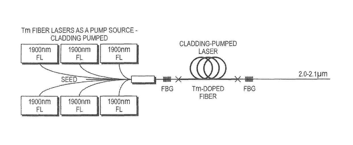
[0021]One embodiment of this invention is to resonantly pump a Tm-doped fiber laser or amplifier in the 1.6-1.9 micron wavelength range. By developing several smaller power fiber lasers operating in the 1.6-1.9 micron region, these lasers can be used as a pump source for generating 2-micron light in a Tm-doped fiber laser. Pumping in this range can yield up to 80-95% quantum efficiencies (QE). With this high efficiency, very little waste heat is gel rated in the fiber, especially compared to pumping with a diode at 795 nm.

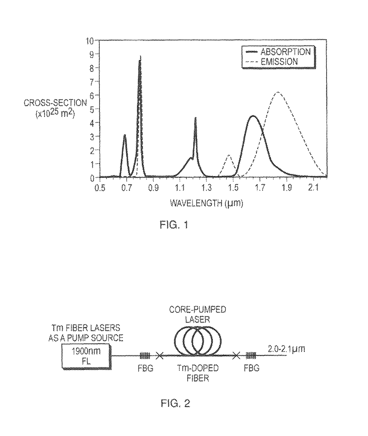
[0022]FIG. 1 is a graphical representation of the wavelengths at which thulium can be pumped and emitted. By pumping in the 1.9 micron range, one can achieve absorption in the fiber which produces a small quantum defect. This results in extremely efficient lasing for significant power scaling.

[0023]FIG. 2 depicts a resonantly-pumped Tm fiber laser, more particularly, a core-pumped laser. In this embodiment, a 1908 nm laser is used to pump the core of another Tm-dop...


PUM


Abstract

In the method of generating high power light with high efficiency and low thermal loading, the improvement comprising the steps of resonantly pumping a first thulium-doped fiber laser with a second thulium-doped fiber last, said second thulium-doped fiber laser having a shorter wavelength than said first thulium-doped fiber laser.

Description

RELATED APPLICATIONS[0001]This application claims the benefit of U.S. Provisional Applications No. 61 / 655,751 filed Jun. 5, 2012 which is herein incorporated by reference in its entirety for all purposes.FIELD OF THE INVENTION[0002]The present invention relates to diode-pumping to generate laser light and, more particularly, to diode-pumped Thulium-doped fiber lasers.BRIEF DESCRIPTION OF PRIOR DEVELOPMENTS[0003]It is common practice to diode-pump a gain medium for laser generation. For instance, thulium-doped fiber lasers (TDFL) are pumped with diodes at 795 nm or with fiber lasers at roughly 1,500 nm. Though the use of a diode increases efficiency, it leads to significant waste heat in a fiber. For high power systems with greater than 100 W of output power, the efficiency is roughly only 50%, and therefore the heat generated in the Tm-doped fiber can be high. For these systems with 100 W of output power or more, the heat generated in the fiber would be on the same order as the opti...

Claims


Application Information

Patent Timeline
Patent Type & Authority Patents(United States)
IPC IPC(8): H01S3/067H01S3/16H01S3/094
CPCH01S3/0675H01S3/094042H01S3/1616H01S3/06754H01S3/094003H01S3/094007H01S3/094011
Inventor CREEDEN, DANIEL J.JOHNSON, BENJAMIN R.
Owner BAE SYST INFORMATION & ELECTRONICS SYST INTERGRATION INC
Why Eureka
Try Eureka