
Environmentally sealed electrical housing assembly with integrated connector

a technology of electrical housing and connector, which is applied in the direction of coupling device details, substation/switching arrangement casing, coupling device connection, etc., can solve the problems of limited space, limited auxiliary power distribution boxes, and difficult packaging of auxiliary boxes

Active Publication Date: 2017-04-11
APTIV TECH LTD
View PDF34 Cites 9 Cited by
  • Summary
  • Abstract
  • Description
  • Claims
  • Application Information

AI Technical Summary

Benefits of technology

The invention describes a method and assembly for creating an environmentally sealed electrical housing with an integrated connector. This involves attaching a non-accessible electrical component to a circuit board, adding a terminal to the circuit board, and integrating a dielectric material over the non-accessible component to form a sealed container while leaving the terminal accessible. A removable electrical component can then be connected to the terminals, and a sealed cover can be added to complete the sealed container. The non-accessible component can be an electrical switching device like an electromechanical relay, and the removable component can include a fusible link. The technical effect is to provide a sealed housing with an integrated connector that is protected from environmental factors and allows for easy connection and replacement of components.

Problems solved by technology

Such auxiliary boxes may be difficult to package within the vehicle due to environmental concerns.
Typically, auxiliary power distribution boxes are not watertight and are limited to being packaged “right side up”, that is the cover on top and connector on the bottom, in an area of the vehicle designated as a low splash zone.

Method used


Image

  • Environmentally sealed electrical housing assembly with integrated connector
  • Environmentally sealed electrical housing assembly with integrated connector
  • Environmentally sealed electrical housing assembly with integrated connector

Examples


Embodiment Construction

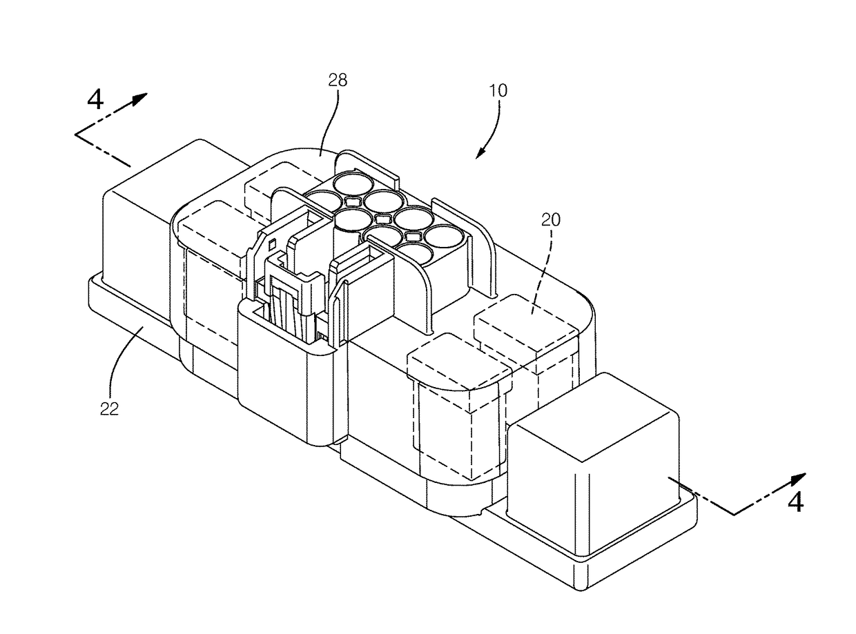
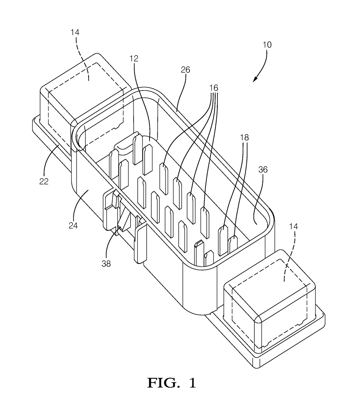
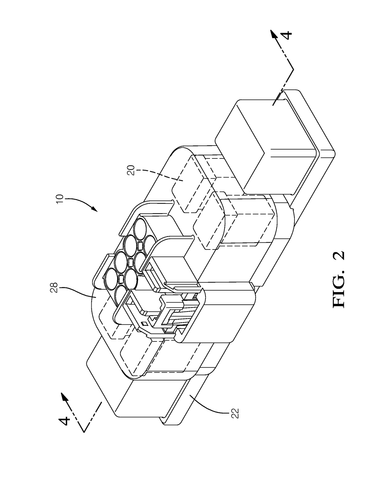
[0017]Described herein is an environmentally sealed electrical housing assembly with an integrated connector, referred to hereafter as a housing assembly. The housing assembly includes a housing that encases selected non-accessible electrical components thereby sealing them from the environment. The housing also includes an opening that allows access to other removable electrical components and with a mating connector body, forms a sealed compartment that protects the removable components from the environment. The housing assembly allows distribution of power switching functions and circuit protection to be distributed to a location near the electrical load instead of form a central location in a vehicle. The housing provides protection of the electrical components from the environment allowing placement of these components outside of a protective enclosure, such as a bussed electrical center. The housing assembly may be placed in areas of harsh splash such as near wheel wells. The ...


PUM

PropertyMeasurementUnit
Fusibilityaaaaaaaaaa

Abstract

An environmentally sealed electrical housing assembly with an integrated connector and a method for manufacturing same is presented. The assembly includes a non-accessible electrical component, such an electromechanical relay, and a plurality of terminals connected to a circuit board. A dielectric housing encases the non-accessible electrical component. The housing is in intimate contact with the non-accessible electrical component, thereby sealing it from the environment. The housing defines an integral perimeter wall that surrounds the terminals, forming a connector shroud. Removable electrical components, such as fuse assemblies, may be attached to the terminals inside the shroud. When a sealed mating connector is attached to the housing, the removable components are also sealed from the environment. The assembly allows distribution of power switching functions and circuit protection to be distributed to a location near the electrical load instead of a central location, such as a bussed electrical center.

Description

TECHNICAL FIELD OF THE INVENTION[0001]The invention generally relates to an electrical housing assembly, and more particularly relates to an environmentally sealed electrical housing assembly with an integrated connector.BACKGROUND OF THE INVENTION[0002]Electromechanical relays that provide electrical load switching in a motor vehicle are typically protected from the environment within enclosures known as bussed electrical centers that are located at central points in the vehicle such as the engine compartment, instrument panel, or luggage compartment (rear trunk). Electrical power is supplied from the vehicle electrical system to the bussed electrical centers. Control signals are transmitted from controllers in the vehicle to the electromechanical relays within the bussed electrical centers to turn power to the loads on and off. Power is supplied to the electromechanical relay switch contacts and the switched electrical power is connected to remote loads through a wiring harness an...

Claims


Application Information

Patent Timeline
IPC IPC(8): H05K3/30H01R13/66H01R43/18H01R13/52H01R13/70H01R43/20
CPCH05K3/30H01R13/6658H01R43/18H01R13/5213H01R13/70H01R43/205H01R2201/26Y10T29/4913H02B1/041H02B1/28
Inventor STERN, ERIC J.MOSBY, WILLIAM J.
Owner APTIV TECH LTD
Learn More