Forward viewing device for a bicycle
- Summary
- Abstract
- Description
- Claims
- Application Information
AI Technical Summary
Benefits of technology
Problems solved by technology
Method used
Image
Examples
second embodiment
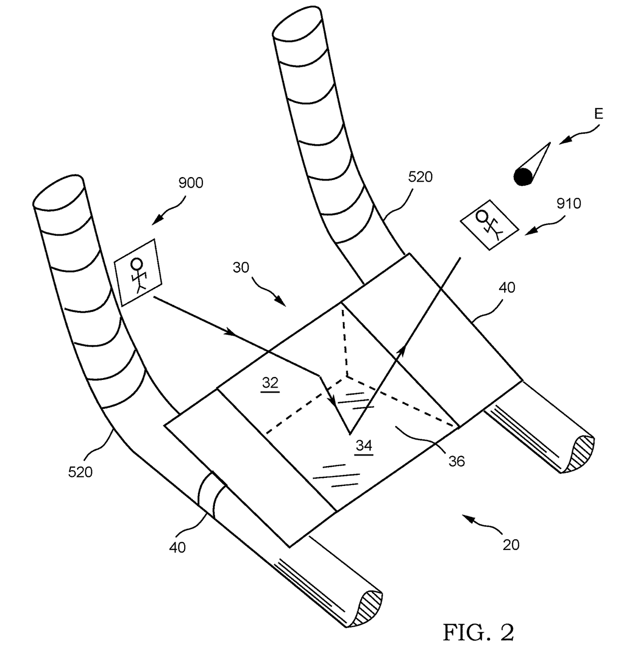
[0038]FIG. 3 is a partial perspective view of forward viewing device 20, in which portions of support 40 and bicycle handlebars 520 are not shown. In the shown embodiment, device 20 includes a plurality of prisms 30 (two shown) each having an end 38. Prisms 30 are positioned with ends 38 adjacent in a manner such that their relative alignment is not adjustable. For example, ends 38 may be joined by optical contact bonding. This arrangement of multiple prism 30 increases the horizontal field of view when smaller prisms 30 are used. The image of the scene 900 is transmitted through multiple first surfaces 32, reflected internally to prisms 30, and transmitted to the cyclist through third surfaces 36 as a normal image 910 with wide horizontal field of view.
third embodiment
[0039]FIG. 4 is a partial perspective view of forward viewing device 20, in which portions of support 40 are not shown for clarity. In this embodiment, first surface 32 is opposite the 90° internal angle of prism 30. Prism 30 is positioned such that the image of scene 900 is normally incident on first surface 32. The image is internally reflected off of second surface 34 and first surface 32, and transmitted through third surface 36 in the cyclist's line of sight. In this arrangement substantially all of third surface 36 is used to transmit image 910, as opposed to the arrangement of FIG. 2 where only the lower half of third surface 36 is used to transmit image 910. In the FIG. 2 arrangement, the upper half of third surface 36 may be blocked from the cyclist's view, as this portion of the surface is used for internal reflection.
fourth embodiment
[0040]FIG. 5 is a partial side elevation view of forward viewing device 20, where support 40 is removed for clarity. In this embodiment, a plurality of prisms 30 are connected to support 40 with a vertical offset. This arrangement is used to increase the vertical field of view. The dashed line indicates the outline of a single large prism with comparable vertical field of view to the two smaller prisms 30 shown. A considerable weight savings is achieved using this arrangement of small prisms 30. Prisms 30 are positioned in a manner such that their relative alignment is not adjustable. For example, prisms 30 are bonded to support 40 at ends 38.
[0041]In an embodiment, device 20 includes only a single optical element (as shown in FIGS. 2 & 4). Optical elements include prisms, mirrors, lenses, and others known in the art. The use of a single optical element eliminates the possibility of individual component misalignment, which would prevent all or a portion of image 910 from being trans...
PUM
 Abstract
Description
Claims
Application Information
 - R&D
- Intellectual Property
- Life Sciences
- Materials
- Tech Scout
- Unparalleled Data Quality
- Higher Quality Content
- 60% Fewer Hallucinations
Browse by: Latest US Patents, China's latest patents, Technical Efficacy Thesaurus, Application Domain, Technology Topic, Popular Technical Reports.
© 2025 PatSnap. All rights reserved.Legal|Privacy policy|Modern Slavery Act Transparency Statement|Sitemap|About US| Contact US: help@patsnap.com


