
Apochromatic optical design

a technology of apochromatic and optical design, applied in the field of lens design, can solve the problems of chromatic aberration, affecting optical performance, and devices that are extremely long, and achieve the effect of superior optical performance, cost and complexity

Active Publication Date: 2017-03-07
BIETRY JOSEPH R
View PDF5 Cites 0 Cited by
  • Summary
  • Abstract
  • Description
  • Claims
  • Application Information

AI Technical Summary

Benefits of technology

[0009]It is an object of the present invention to advance the art of telescopic and other types of imaging that have a narrow field of view. With this object in mind, the present disclosure describes an apochromatic optical design that provides superior optical performance without the added cost and complexity of triplet lens arrangements and without requiring highly anomalous glass types.
[0010]It is a feature of the present invention that it provides good color correction using only a small number of lenses and employing anomalous glass at a point in the optical system where a smaller lens can be used.

Problems solved by technology

Optical systems characterized by a relatively narrow field of view, such as refracting telescopes and various long-range viewing apparatus of similar design, have a number of characteristic limitations affecting optical performance.
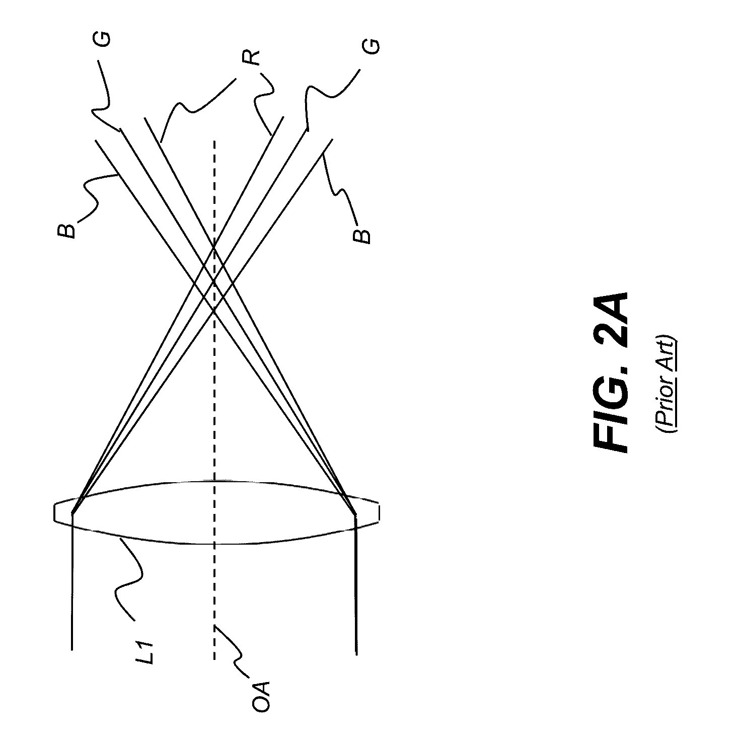
Among these is chromatic aberration, largely due to the dispersive properties of glass.
Use of a very slow focal ratio (high ratio of focal length to lens diameter or f-number), on the order of f / 150 reduces the severity of the aberration but results in devices that are extremely long and, at best, mechanically cumbersome.
In the Newtonian reflecting telescope, mirrors are used in place of lens elements in order to reduce chromatic aberration; however, this approach tends to increase a number of monochromatic aberrations.
At the same time, however, these highly anomalous glass types are increasingly expensive and can be difficult to fabricate.
This design, however, does not provide well-behaved control of color.
Significantly, the Duplov arrangement requires that the track length of a telescope that is designed using these optics must be from about 1.75 to 2.5 times the focal length, which is disadvantageous.

Method used


Image

  • Apochromatic optical design
  • Apochromatic optical design
  • Apochromatic optical design

Examples


Embodiment Construction

[0032]The present description is directed in particular to elements forming part of, or cooperating more directly with, apparatus in accordance with the invention. It is to be understood that elements not specifically shown or described may take various forms well known to those skilled in the art.

[0033]Where they are used, the terms “first”, “second”, and so on, do not necessarily denote any ordinal, sequential, or priority relation, but are simply used to more clearly distinguish one element or set of elements from another, unless specified otherwise.

[0034]In the context of the present disclosure, the term “coupled” is intended to indicate a mechanical association, connection, relation, or linking, between two or more components, such that the disposition of one component affects the spatial disposition of a component to which it is coupled. For mechanical coupling, two coupled components need not be in direct contact, but can be linked through one or more intermediary components....


PUM


Abstract

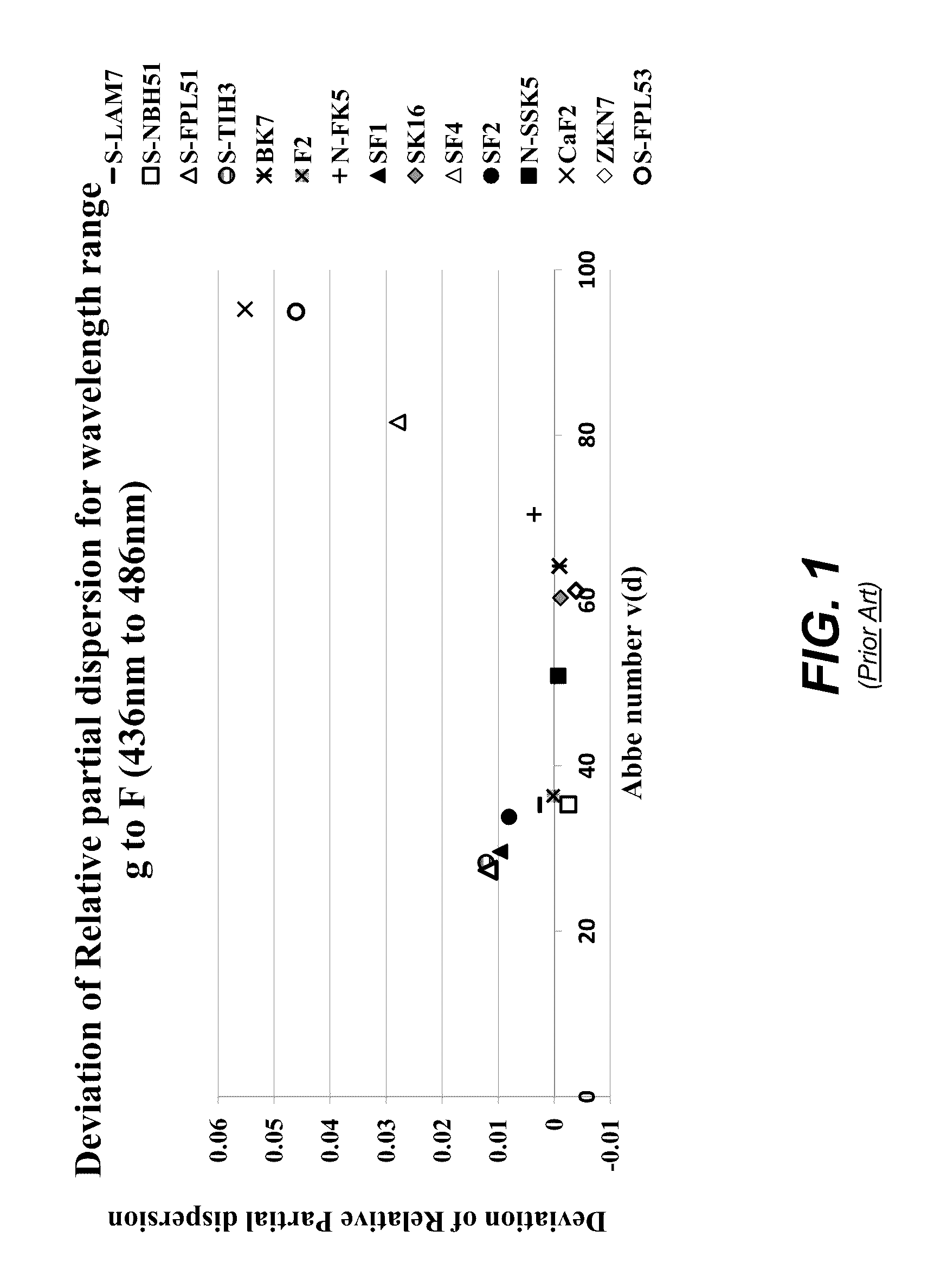
An apochromatic imaging system has an object-side lens group having at least an object-side lens element with positive refractive power and formed from a flint glass material with deviation of relative dispersion −0.013<ΔPg,F<+0.013 and an Abbe number less than 50. A middle lens group has at least a second lens element and a third lens element, wherein, one of the second and third lens elements has deviation of relative dispersion −0.013<ΔPg,F<0.013 and the other of the second and third lens elements has deviation of relative dispersion 0.013<ΔPg,F<0.04. An image-side lens group has at least a fourth lens element.

Description

FIELD OF THE INVENTION[0001]This invention generally relates to design of optical systems and more particularly relates to lens design for refracting telescopes and similar devices having a narrow field of view.BACKGROUND OF THE INVENTION[0002]Optical systems characterized by a relatively narrow field of view, such as refracting telescopes and various long-range viewing apparatus of similar design, have a number of characteristic limitations affecting optical performance. Among these is chromatic aberration, largely due to the dispersive properties of glass. Dispersion of an optical substrate causes the refraction of a lens to vary with wavelength, so that, for conventional optical glass, the index of refraction is higher for short wavelengths and decreases as wavelength increases. As a result of chromatic aberration, blue light rays come to focus closer to the lens than do red light rays.[0003]The problem of chromatic aberration in telescopes has been addressed in a number of ways....

Claims


Application Information

Patent Timeline
Patent Type & Authority Patents(United States)
IPC IPC(8): G02B23/00G02B27/00G02B9/34
CPCG02B23/00G02B27/005G02B9/34
Inventor BIETRY, JOSEPH R.
Owner BIETRY JOSEPH R
Learn More