
Adaptive error correction code for optical super-channels

a super-channel and error correction technology, applied in the field of coherent optical communication systems, can solve the problems of increasing serial adc sampling rate, changing the nonlinearity-induced distortion of other channels, and difficult to implement single-wavelength coherent detection at data rates greater than 100 gbit/s, so as to achieve the effect of improving performance over optical channels

Active Publication Date: 2017-02-28
MITSUBISHI ELECTRIC RES LAB INC
View PDF4 Cites 4 Cited by
  • Summary
  • Abstract
  • Description
  • Claims
  • Application Information

AI Technical Summary

Benefits of technology

[0010]Additionally or alternatively, some embodiments allow for the transmission of a super-channel over several non-adjacent wavelengths in a point-to-point link, to improve performance over optical channels where the noise and distortion power spectrum are not flat.

Problems solved by technology

However, an increase in serial ADC sampling rates is difficult to implement for single-wavelength coherent detection at data rates greater than 100 Gbit / s.
However, the small size of the gap between frequencies of different sub-channels cause nonlinearity of noise in the sub-channels, i.e., each sub-channel receives different nonlinearity-induced phase noise causing non uniformity in the bit-error-ratio (BER) across the sub-channels.
However, the increase of the transmission power for one channel also changes the nonlinearity-induced distortion of other channels.
Therefore, it is difficult to adjust the power levels of all the sub-channels in the same fiber to meet the BER requirements.

Method used


Image

  • Adaptive error correction code for optical super-channels
  • Adaptive error correction code for optical super-channels
  • Adaptive error correction code for optical super-channels

Examples


Embodiment Construction

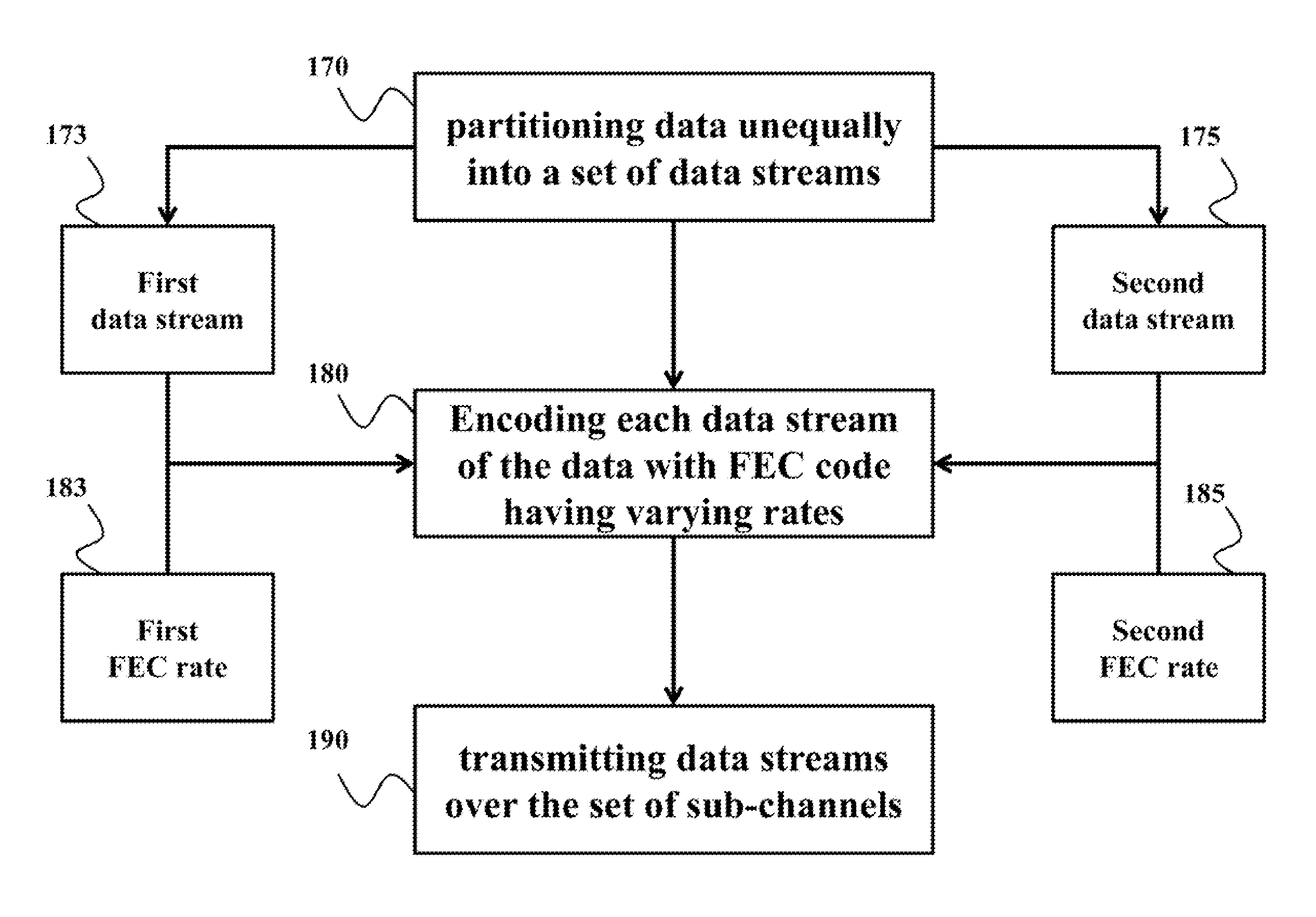
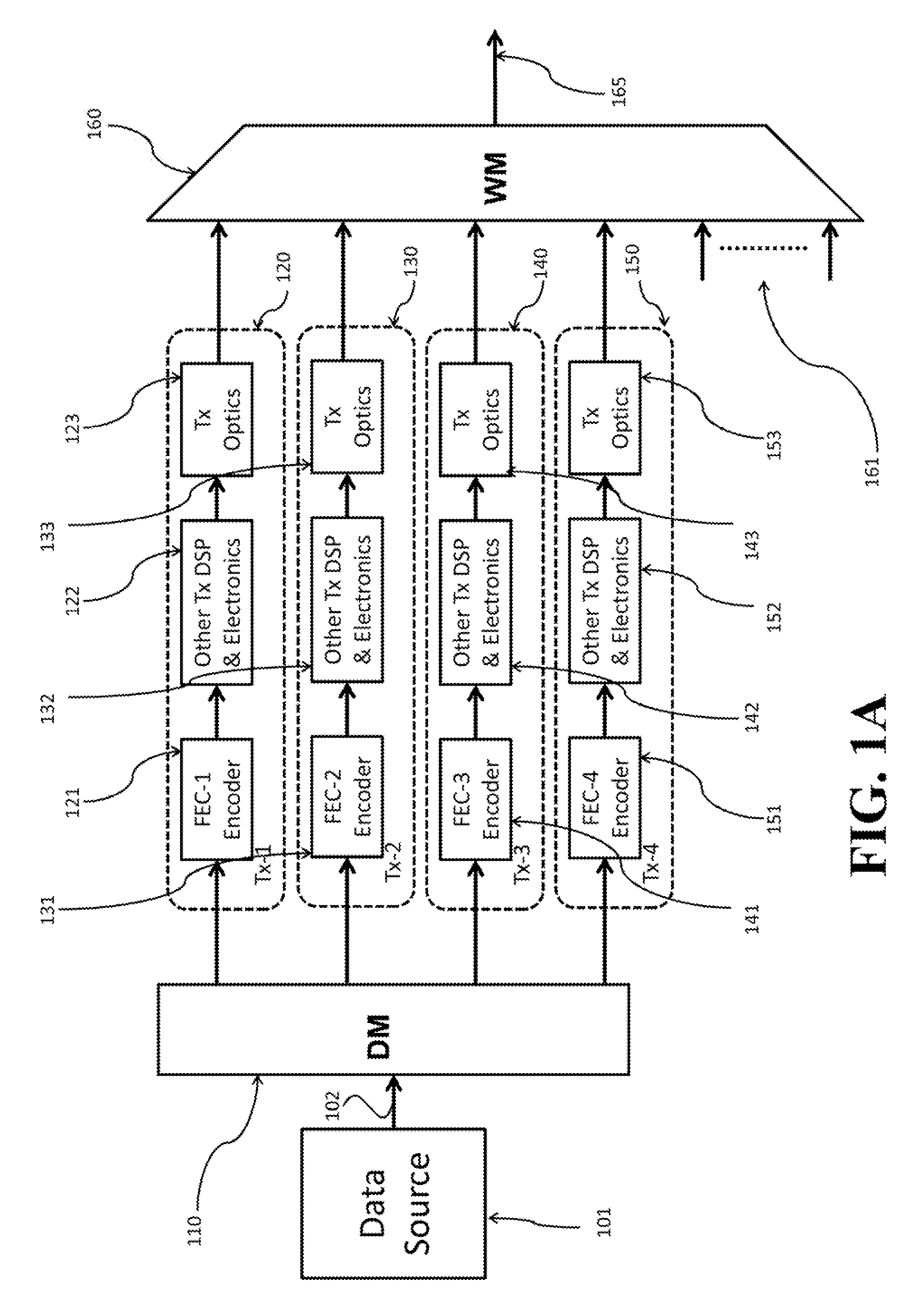
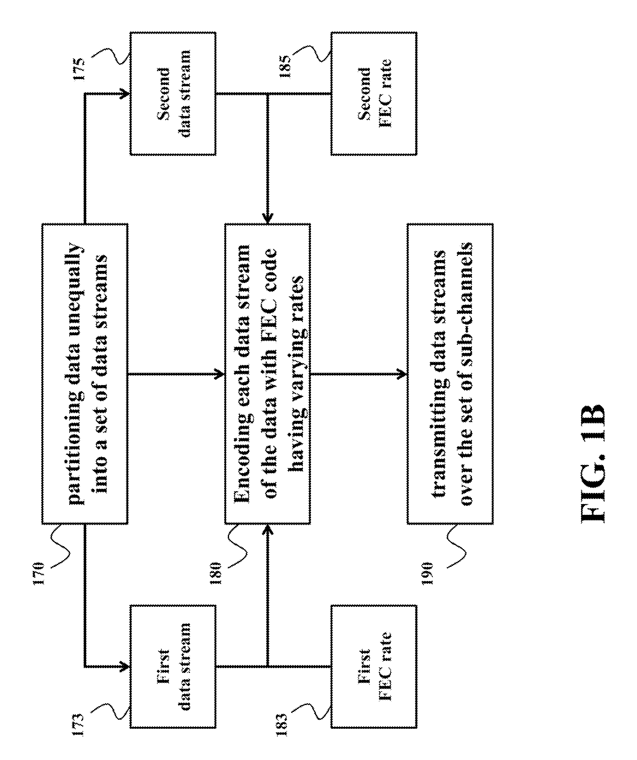
[0021]FIG. 1A shows a block diagram of a super-channel transmitter for transmitting data to a receiver over an optical super-channel formed by a set of sub-channels of different wavelengths. FIG. 1B shows a flow chart of a method for transmitting the data that can be implemented by the super-channel transmitter of FIG. 1A.

[0022]Some embodiments of the invention are based on a realization that the data transmitted over the super-channel can be partitioned unequally into a set of data streams for transmission over the sub-channels. Usually, the bit rate and the size of the data transmitted over the entire super-channel are fixed. However, according to the embodiments, only the bit rates are fixed for the sub-channels, and the size of the transmitted data streams can vary for different sub-channels as long as the sum of the data transmitted over all sub-channels equals the fixed data transmitted over the super-channel.

[0023]According to various embodiments of the invention, the super-c...


PUM


Abstract

A method for transmitting data over an optical super-channel partitions the data unequally into a set of data streams for transmission over the set of sub-channels of the super-channel, such that a size of a first data stream for transmission over a first sub-channel is different than a size of a second data stream of the data for transmission over a second sub-channel. The method encodes each data stream of the data with an error correction code (ECC) having different ECC rates to produce a set of encoded data streams and transmits concurrently the set of encoded data streams over the set of sub-channels of the super-channel. Accordingly, the method uses an adaptive ECC for optical super-channels, such that a first ECC rate for encoding the first data stream is different than a second ECC rate for encoding the second data stream.

Description

FIELD OF THE INVENTION[0001]This invention relates generally to coherent optical communications systems, and more particularly to transmitting data over an optical super-channel.BACKGROUND OF THE INVENTION[0002]Coherent optical communications enable data to be transmitted over long haul (typically >2,000 kin) optical transmission networks at higher data rates. A coherent detector requires that the received phase modulated optical signal is digitized for a digital signal processor (DSP). Digitizing the received signal requires a high speed analog-to-digital converter (ADC). However, an increase in serial ADC sampling rates is difficult to implement for single-wavelength coherent detection at data rates greater than 100 Gbit / s.[0003]A super-channel is an evolution in dense wavelength division multiplexing (DWDM) in which multiple coherent optical carriers are combined on a single super-channel at a higher data rate, and is brought into service in a single operational cycle. Rather ...

Claims


Application Information

Patent Timeline
Patent Type & Authority Patents(United States)
IPC IPC(8): H03M13/00H04L1/00H04J14/02H04B10/079
CPCH04L1/0041H04B10/07953H04J14/02H04J14/0257H04J14/0298H04L1/0009H04L1/0045H04J2203/0076
Inventor KOJIMA, KEISUKEPARSONS, KIERANMILLAR, DAVIDKOIKE-AKINO, TOSHIAKI
Owner MITSUBISHI ELECTRIC RES LAB INC
Learn More