Eureka AIR delivers breakthrough ideas for toughest innovation challenges, trusted by R&D personnel around the world.

System and method for producing high quality seismic records within bore holes

a technology of seismic record and production method, which is applied in the field of system and method for producing high-quality seismic record within bore holes, can solve the problems that none of these types of sound sources have proved to be practical or robust enough to be used over extended periods of time, and achieve the effect of high quality

Inactive Publication Date: 2017-02-28
CHELMINSKI STEPHEN
View PDF18 Cites 0 Cited by
  • Summary
  • Abstract
  • Description
  • Claims
  • Application Information

AI Technical Summary

Benefits of technology

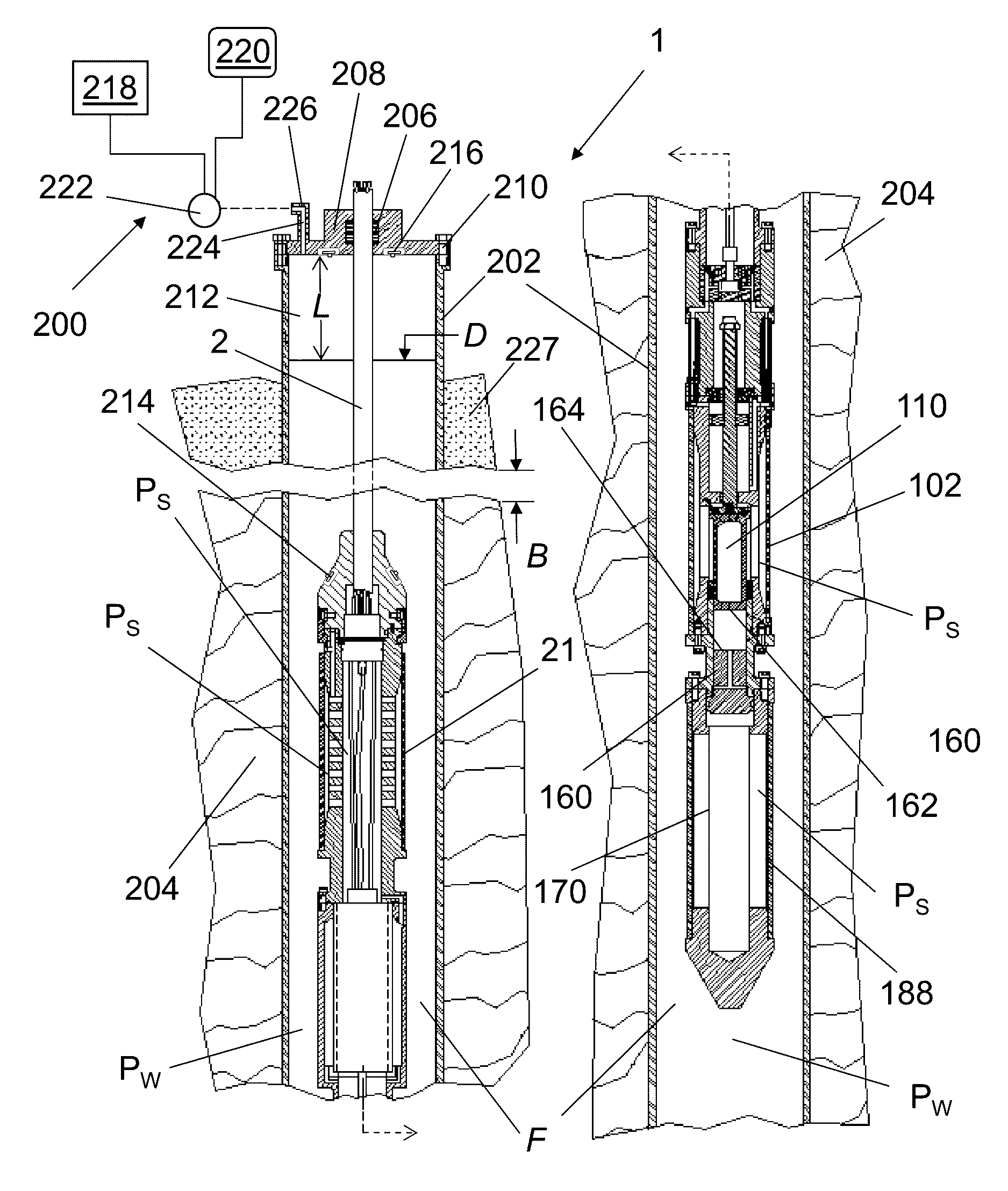
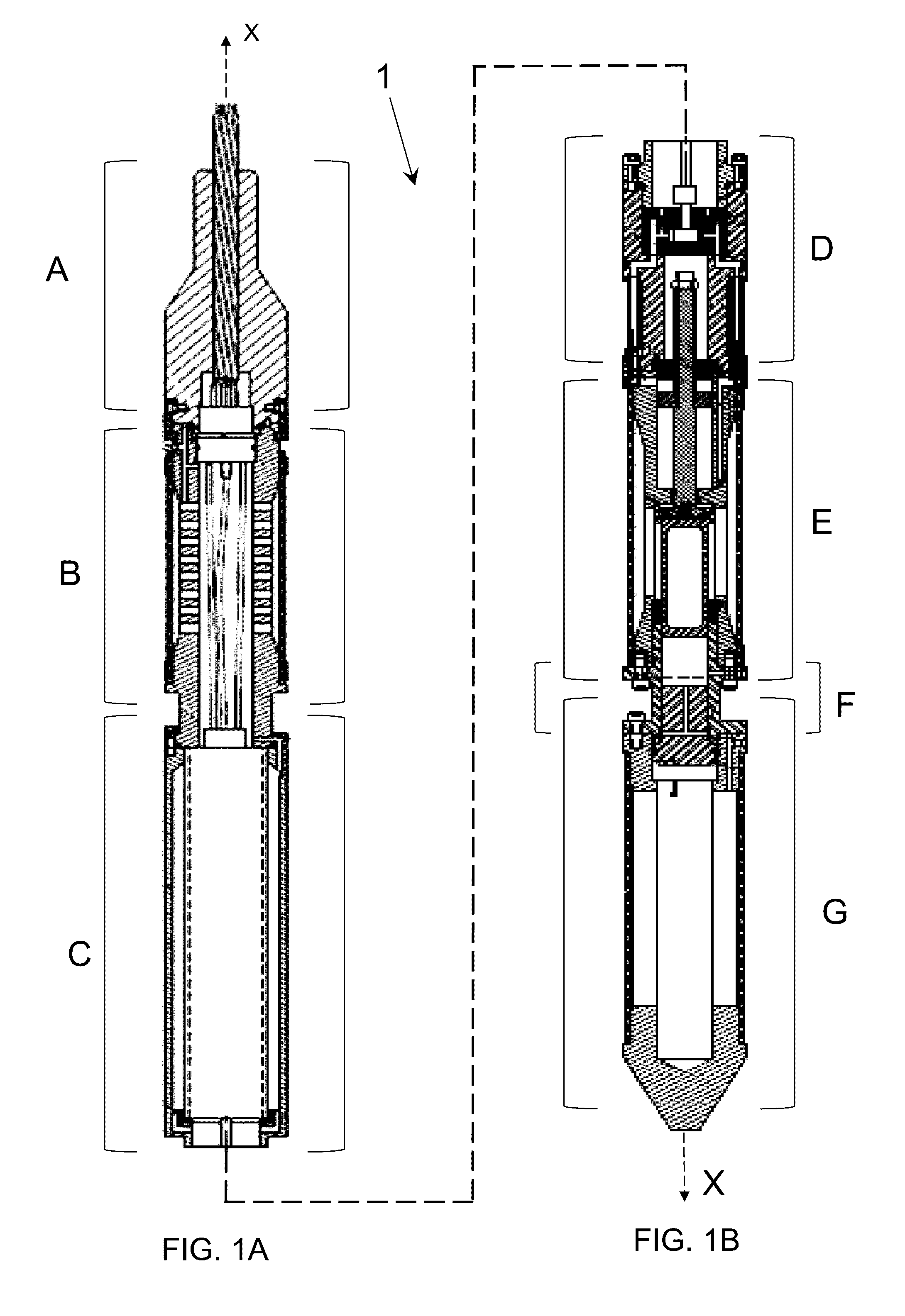
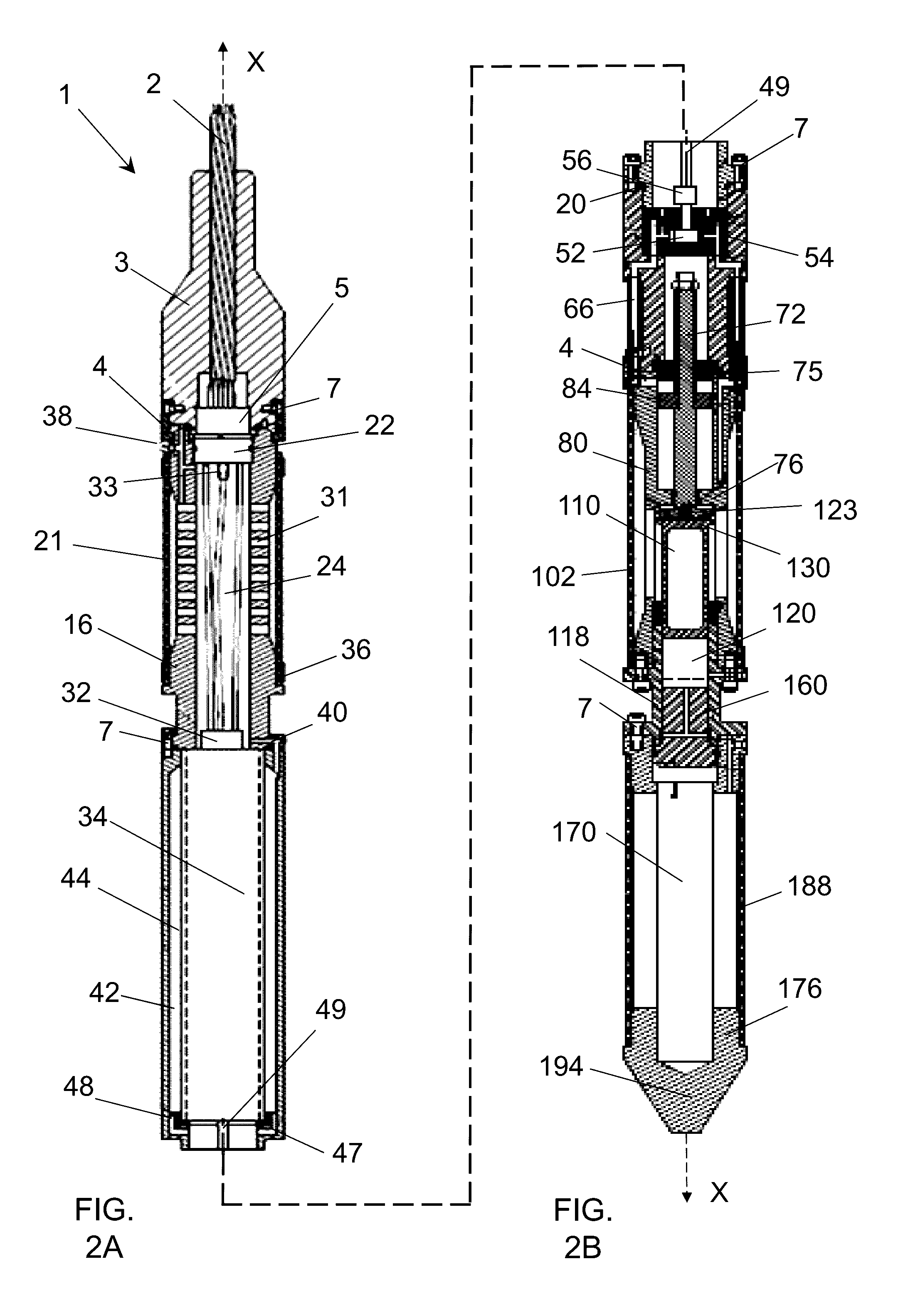
[0004]A system and method of providing high quality seismic records from an impulse type of down-hole sound source designed to be robust as well as provide a practical tool to provide sound pulses for geophysical studies of the earth surrounding bore holes is here-with provided. The present invention further provides a system and method of obtaining seismic records using an impulsive sound source within a bore hole comprising the steps of artificially pressurizing the bore hole to obtain acceptable high quality seismic records. The present invention utilizes a free piston which is accelerated by the hydrostatic pressure of a fluid. Upon actuation of the free piston, the free piston moves through an isolated partially fluid filled piston chamber and strikes a sound transmitting anvil sending a sound pulse into an adjacent sound transmission chamber that is filled with light weight oil and surrounded by an elastomeric bladder. The sound pulse from the accelerating anvil moves the elastomeric bladder producing a sound wave that is emitted out through the fluid and ambient walls of the bore hole and into geological surrounding structures. In preparation for firing, an electric motor powered hydraulic pump, pumps hydraulic fluid to move a reset piston assembly to position a latching seal flange of the assembly into a receiving cup of a free piston. A check valve assembly within the flange provides for the evacuation of fluid within the receiving cup forming a vacuum seal that allows the reset piston assembly to draw the free piston through a high pressure fluid filled chamber and into a ready to fire position. The free piston is drawn to a stop point that breaks the vacuum and allows high pressure fluid within the chamber to rapidly accelerate the free piston against the anvil piston with the impulse providing the sound transmission.
[0005]The impulsive sound source is designed in sections aligned end to end with a first cable termination module housing an umbilical cable and providing for the cable to be attached to and detached from the source. The cable is terminated at a two piece connector that has a first half portion within the upper module detachable from a second half portion that is mounted within the next module, an expansion chamber. The expansion chamber is enclosed with an elastomeric bladder to provide for changes in pressures within the source and assist in the absorption of vibrations as the source is fired. The expansion chamber serves as a reservoir for hydraulic fluid to operate the reset piston assembly. The expansion chamber also houses a set of power cables that extend through the chamber and are affixed to run an electric motor housed in the next module. The electric motor drives a hydraulic pump housed within a next module. The hydraulic pump takes fluid from and returns fluid to the reservoir of the expansion chamber and provides fluid to move the reset piston assembly that prepares the source for firing. The reset piston assembly module also houses the high pressure fluid implosion chamber for the free piston. The impact chamber is an open cylinder that houses the anvil and receives the fired free piston from the implosion chamber that strikes the anvil forcing the anvil a short distance into the sound transmission chamber transmitting the sound pulse to the elastomeric bladder that encloses the transmission chamber. The bladder propagates the sound through the fluid of the bore hole and the surrounding geological structure.
[0013]The present invention is further related to a method of generating a sound pulse within a bore hole through a manual or automated process, comprising the steps of extending an umbilical cable to support a cylindrical housing of a sound source; storing hydraulic fluid in a reservoir within the housing; supplying a hydraulic pump from the reservoir; controlling the hydraulic pump using an electric motor powered from the umbilical cable; filling a hydraulic cylinder using the hydraulic pump; moving a reset piston within a fluid filled implosion chamber using the hydraulic cylinder; seating the reset piston within a cup formed in the upper portion of a free piston; evacuating fluid from the cup forming a vacuum to draw the free piston using the reset piston to a ready to fire position; preventing travel of the free piston and pulling the reset piston from the cup thereby breaking the vacuum and accelerating the free piston to strike an anvil within an impact chamber to generate a sound pulse; transmitting the sound pulse through a fluid filled sound transmission chamber to an elastomeric bladder to propagate the pulse out and through the fluid filled bore hole and into the surrounding geological structures.

Problems solved by technology

Geophysical studies between bore holes or between bore holes and the ground surface have been done in the past using small charges of explosive impulsive sources and vibratory sound sources, but none of these types of sound sources have proved to be either practical or robust enough to be used over extended periods of time.

Method used


Image

  • System and method for producing high quality seismic records within bore holes
  • System and method for producing high quality seismic records within bore holes
  • System and method for producing high quality seismic records within bore holes

Examples


Embodiment Construction

[0048]The present invention is an impulsive type sound source for creating sound pulses which can be used for seismic surveys between liquid filled bore holes in the ground such as water wells, oil wells and / or bore holes for geological studies. The present invention is further related to a system and method of artificially pressurizing the bore hole to obtain adequate and consistent pressures to operate the sound source to sufficient sound output levels to obtain acceptable high quality seismic records.

[0049]The present invention provides a sleek modular design of an impulsive sound source 1 to make the system easier for transportation and insertion of the source into wells and bore holes for seismic analysis deep within the ground. The impulsive sound source 1 may be of any diameter and dimension suitable for the requirements of a geological survey with components of acceptable materials to withstand the high temperatures and pressures within water wells, oil wells and / or the bore...


PUM


Abstract

A sound source for geophysical studies of the earth for oil, gas and other natural resource exploration and more specifically a streamlined design of a hydraulically controlled impulsive sound source that may be inserted into oil wells and bore holes and a system and method for obtaining high quality seismic records from the impulsive sound source by adjusting and maintaining pressures within the well or bore hole.

Description

RELATED APPLICATIONS[0001]This application is a continuation-in-part of U.S. patent application Ser. No. 14 / 052,731 filed Oct. 12, 2013 that claims the benefit of U.S. Provisional Application No. 61 / 713,945 filed Oct. 15, 2012 entitled Method and Apparatus for Producing Sound Pulses within Bore Holes which is incorporated herein by reference in its entirety. This application further claims the benefit of U.S. Provisional Application No. 61 / 987,081 filed May 1, 2014 entitled, System and Method for Energizing an Impulsive Type Down-Hole Source which are each incorporated herein by reference in their entireties.FIELD OF THE INVENTION[0002]The present invention is related to a system and method for obtaining high quality seismic records from an impulse type sound source for geophysical studies of geological structures surrounding bore holes. The present invention is further related to a system and method of artificially pressurizing the bore hole and to adjusting and maintaining pressur...

Claims


Application Information

Patent Timeline
Patent Type & Authority Patents(United States)
IPC IPC(8): G01V1/40E21B47/06G01V1/147G01V1/46G01V1/28E21B47/00
CPCG01V1/147G01V1/40
Inventor CHELMINSKI, STEPHEN
Owner CHELMINSKI STEPHEN
Why Eureka
Eureka Blog
Learn More