
Power converter with self-driven synchronous rectifier control circuitry

a technology of synchronous rectifier and control circuit, which is applied in the direction of power conversion systems, efficient power electronics conversion, climate sustainability, etc., can solve the problems of significant loss of such a bridge rectifier, and achieve the effect of significantly reducing the loss of diode voltage drop

Active Publication Date: 2017-02-21
BEL POWER SOLUTIONS INC
View PDF20 Cites 4 Cited by
  • Summary
  • Abstract
  • Description
  • Claims
  • Application Information

AI Technical Summary

Benefits of technology

The present invention is a switch-mode AC-DC power converter that reduces diode voltage drop losses by using parallel MOSFETs instead of diodes. The use of MOSFETs results in significantly lower power loss and higher efficiency of the power converter. The technical effect of this invention is to better match the performance of diodes with the needs of a power converter, leading to improved efficiency and reliability.

Problems solved by technology

However, losses on such a bridge rectifier may be significant.

Method used


Image

  • Power converter with self-driven synchronous rectifier control circuitry
  • Power converter with self-driven synchronous rectifier control circuitry
  • Power converter with self-driven synchronous rectifier control circuitry

Examples


Embodiment Construction

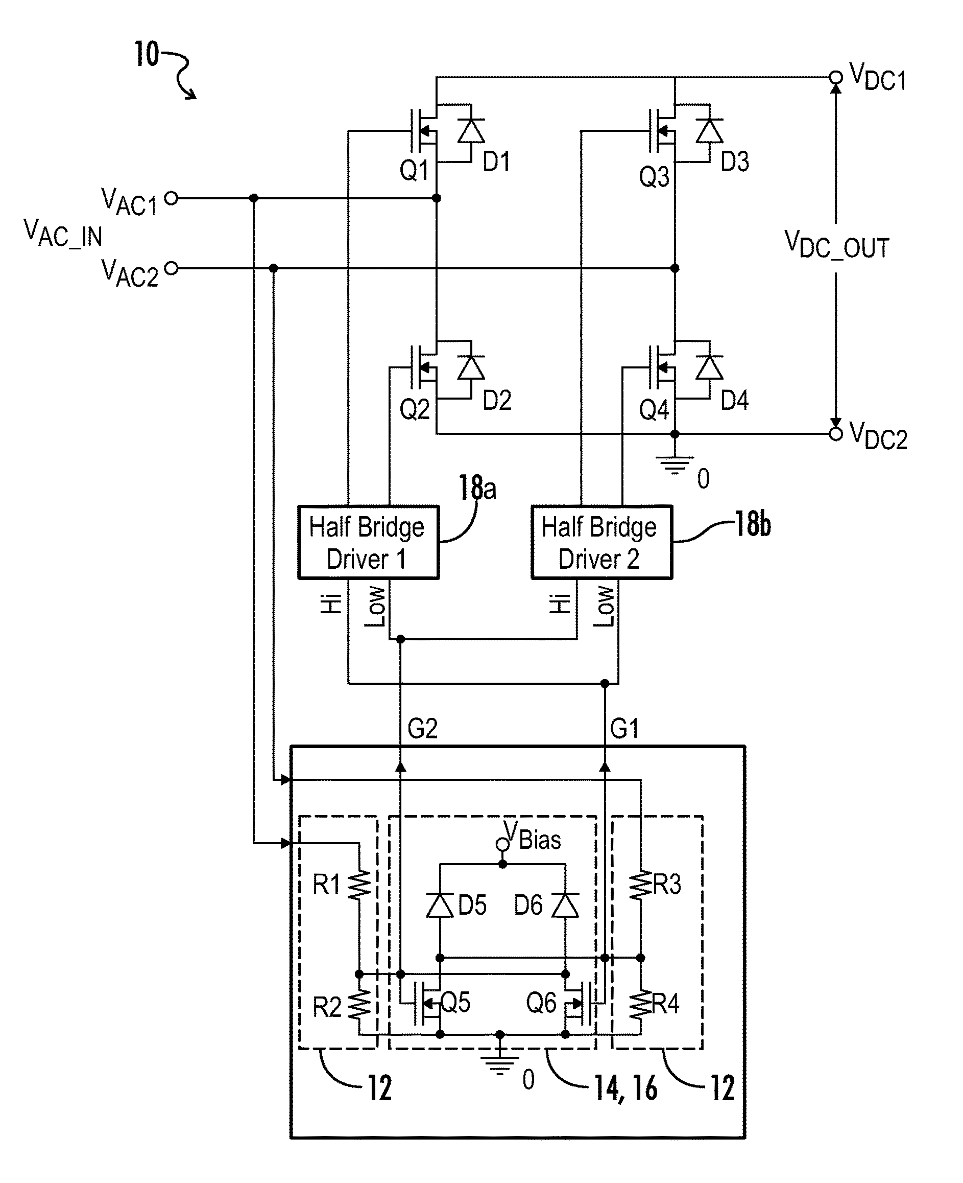
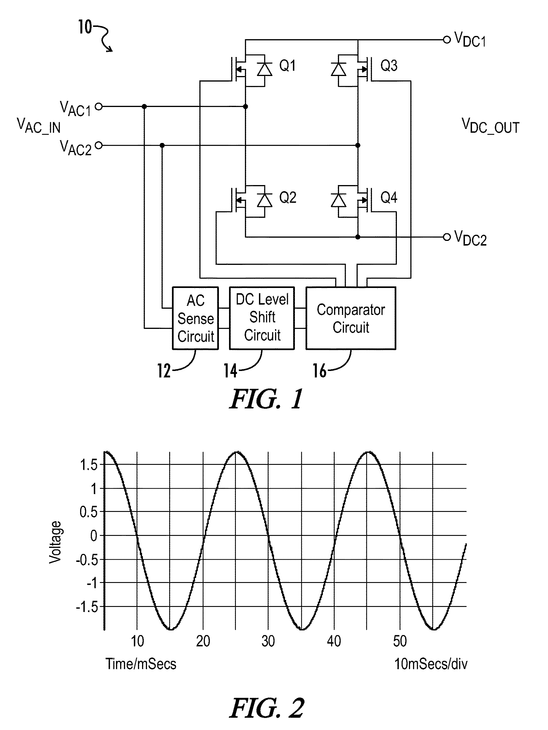
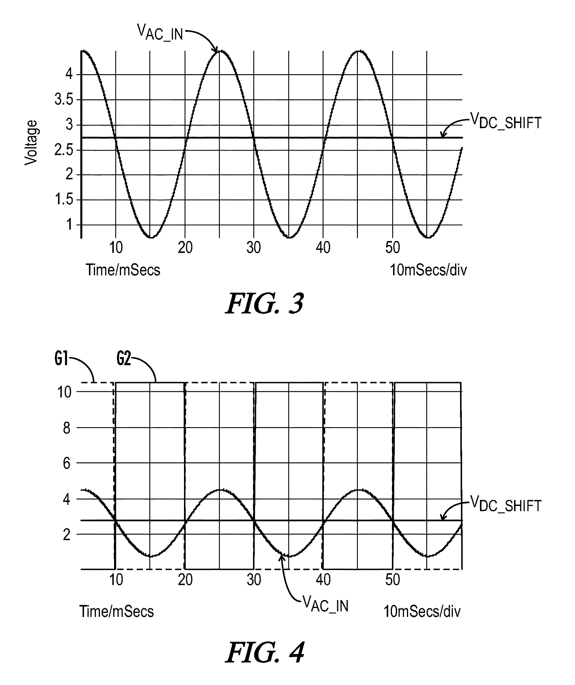
[0029]Referring generally to FIGS. 1-12, various embodiments of a power converter with an active bridge MOSFET rectifier, active bridge control circuitry and methods of operation may now be described. Where the various figures may describe embodiments sharing various common elements and features with other embodiments, similar elements and features are given the same reference numerals and redundant description thereof may be omitted below.

[0030]Referring first to FIG. 1, an embodiment of a power converter 10 is shown coupled on a first end to first and second AC input terminals VAC1 and VAC2 and on a second end to first and second DC terminals VDC1 and VDC2. A first active rectifier bridge includes first and second switching elements Q1 and Q2 as synchronous rectifiers coupled in series across the first and second DC terminals, with the first AC terminal VAC1 coupled to a node between the first and second switching elements. A second active rectifier bridge includes third and fourt...


PUM


Abstract

An AC-DC power converter is provided with two pairs of self-driven synchronous rectifier switches in addition to, or in place of, diode bridge rectifiers for boosting efficiency and reducing cost. An AC sensing circuit is coupled to AC input terminals, and a DC level shifting circuit applies a DC offset to an AC input signal received via the sensing circuit. A comparator circuit determines positive and negative half waves of the AC input signal relative to the DC offset value. Gate drive signals are provided for driving a first set of parallel rectifier switches during a positive half cycle of the AC input signal, and for driving a second and opposing pair of parallel rectifier switches during a negative half cycle of the AC input signal. In an embodiment, high side gate drive signals may be electrically isolated from the active rectifier control circuitry.

Description

CROSS-REFERENCES TO RELATED APPLICATIONS[0001]This application claims benefit of the following patent application which is hereby incorporated by reference: U.S. Provisional Patent Application No. 61 / 787,923, filed Mar. 15, 2013.[0002]A portion of the disclosure of this patent document contains material that is subject to copyright protection. The copyright owner has no objection to the reproduction of the patent document or the patent disclosure, as it appears in the U.S. Patent and Trademark Office patent file or records, but otherwise reserves all copyright rights whatsoever.BACKGROUND OF THE INVENTION[0003]The present invention relates generally to switch-mode power converters. More particularly, the present invention relates to power supplies using synchronous rectifier circuitry in place of a diode bridge. Even more particularly, the present invention relates to control circuitry for driving synchronous rectifiers according to input voltage phase.[0004]Various switch-mode powe...

Claims


Application Information

Patent Timeline
Patent Type & Authority Patents(United States)
IPC IPC(8): H02M7/219
CPCH02M7/219H02M2007/2195Y02B70/1408H02M7/2195Y02B70/10
Inventor TEREN, ANDREJVRANKA, MARIANPIETKA, MARTINKEUNG, LEE TAI
Owner BEL POWER SOLUTIONS INC
Learn More