Actuator and vehicle lighting device

a technology for actuators and vehicles, applied in the field of circuit units, can solve the problems of circuit board likely to be bent, circuit board likely to be distorted, circuit board likely to be damaged, etc., to suppress the manufacturing cost and environmental impact, reduce the amount of solder, and improve the appearance of the soldered part

Inactive Publication Date: 2017-02-21
KOITO MFG CO LTD
View PDF14 Cites 1 Cited by
  • Summary
  • Abstract
  • Description
  • Claims
  • Application Information

AI Technical Summary

Benefits of technology

[0006]It is therefore a first object of the present invention to suppress stress to be applied to a circuit board to be accommodated in a case and to prevent a damage of a motor driving circuit mounted on the circuit board.
[0094]According to the above configuration, it is possible to prevent an area in which the solder does not exist. Thereby, it is possible to improve an appearance of the soldered part, thereby avoiding a situation where the soldered part is wrongly recognized as a defect. Also, it is possible to reduce an amount of the solder to be used, thereby suppressing the manufacturing cost and the environmental impact. Therefore, it is possible to accomplish the corresponding effects while preventing the damage of the circuit board or mounted circuit element.

Problems solved by technology

At this time, the circuit board is likely to be bent due to the pressing force, so that a wiring, a contact, an electronic component and the like configuring the driving circuit may be damaged.
Also, even after the circuit board is arranged in the mounting area, the circuit board is continuously applied with stress from the surrounding protrusions, so that the circuit board is likely to be distorted.
The generated distortion may also be a cause of the damage of the driving circuit.
The damage of the driving circuit may cause a failure in an operation of the actuator and an operation of the lighting device having the actuator.

Method used


Image

  • Actuator and vehicle lighting device
  • Actuator and vehicle lighting device
  • Actuator and vehicle lighting device

Examples


Embodiment Construction

[0111]An illustrative embodiment of the present invention will be described in detail with reference to the accompanying drawings. Meanwhile, in the respective drawings used in the below descriptions, a scale is appropriately changed so as to show each member as a recognizable size.

[0112]FIG. 1 illustrates a part of a headlight device 1, which is an example of the lighting device according to an illustrative embodiment of the present invention, as seen from a vertically sectioned left side. The headlight device 1 is a device mounted at a front part of a vehicle and configured to illuminate the front of the vehicle. The headlight device 1 has a housing 2, and a translucent cover 4 mounted to the housing 2 and configured to define a lamp chamber 3. In the lamp chamber 3, a lamp unit 10 is arranged.

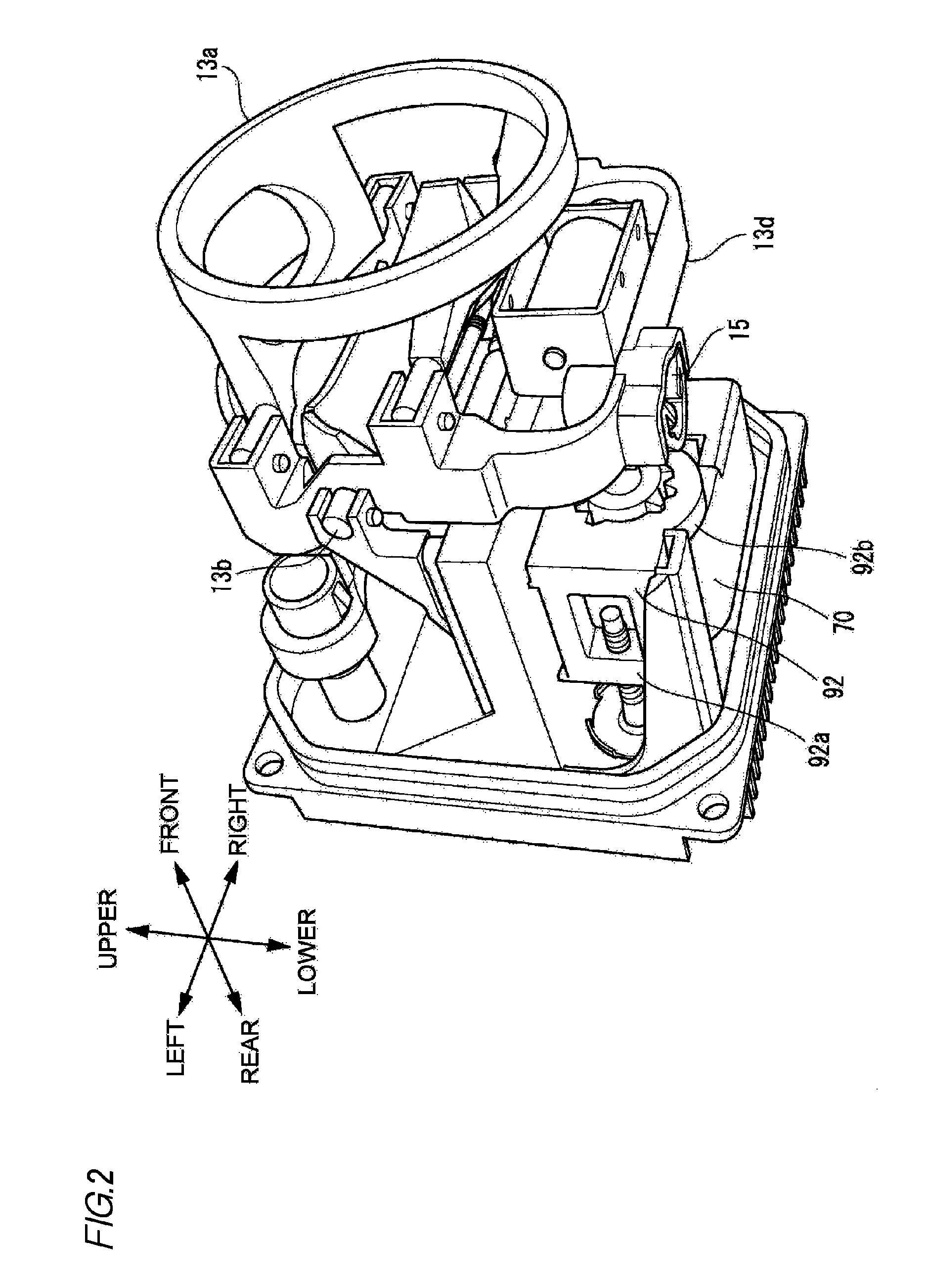
[0113]The lamp unit 10 has a heat sink 11, a light source unit 12, a lens holder 13, a projection lens 14, an actuator 17 and an aiming mechanism 19.

[0114]The heat sink 11 has a back plate p...


PUM


Abstract

A motor causes a shaft of an actuator to be displaced in an axis direction thereof, at least part of a circuit for driving the motor being mounted on a circuit board. A notch is formed in an end edge of the circuit board. A protrusion is formed inside a case. The protrusion is fitted into the notch, whereby the circuit board is independently supported inside the case.

Description

TECHNICAL FIELD[0001]The present invention relates to a circuit unit having a terminal mounted on a circuit board. Also, the present invention relates to an actuator having the circuit unit and configured to displace a shaft in an axis direction thereof, thereby displacing a target. Further, the present invention relates to a vehicle lighting device of which a part can be displaced in a predetermined direction by a shaft included in the actuator.BACKGROUND ART[0002]Patent Document 1 discloses a kind of the actuator. A shaft, a motor, a circuit board and a gear mechanism are accommodated in a case. A part of the shaft protrudes outside the case. At least a part of a circuit configured to drive the motor is mounted on the circuit board. A driving force of the motor is transmitted to the shaft by the gear mechanism and the shaft is displaced in an axis direction thereof. A tip of the shaft positioned outside the case is coupled to a part of a lighting device mounted to a vehicle. As th...

Claims


Application Information

Patent Timeline
Patent Type & Authority Patents(United States)
IPC IPC(8): B60Q1/115H02K5/22H05K5/00H05K5/02B60Q1/076H02K5/04F21S8/10
CPCB60Q1/076H02K5/04H02K5/225H02K11/33H05K5/0017H05K5/0217B60Q1/115F21S48/1742H05K2201/09145F21S45/48H05K1/02H02K7/06H02K2211/03H02K11/21F21S41/657F21S45/50F21S41/25F21S41/635F21S41/19F21S41/39H02K7/116H02K5/16H05K1/116H05K1/184
Inventor IWAI, KATSUTOSHIOTAKA, HIROSHIKATO, TAKAYUKI
Owner KOITO MFG CO LTD
Why Eureka
Try Eureka