DC-DC converter
a converter and converter technology, applied in the direction of electric variable regulation, process and machine control, instruments, etc., can solve the problems of increasing switching loss, generating conduction loss in the transformer and the switching element, and not contributing to the power of current, so as to reduce the size, weight and cost of the converter, the effect of enhancing power conversion efficiency
- Summary
- Abstract
- Description
- Claims
- Application Information
AI Technical Summary
Benefits of technology
Problems solved by technology
Method used
Image
Examples
embodiment 1
[0022]Hereinafter, a DC-DC converter according to Embodiment 1 of the present invention will be explained based on the drawings.
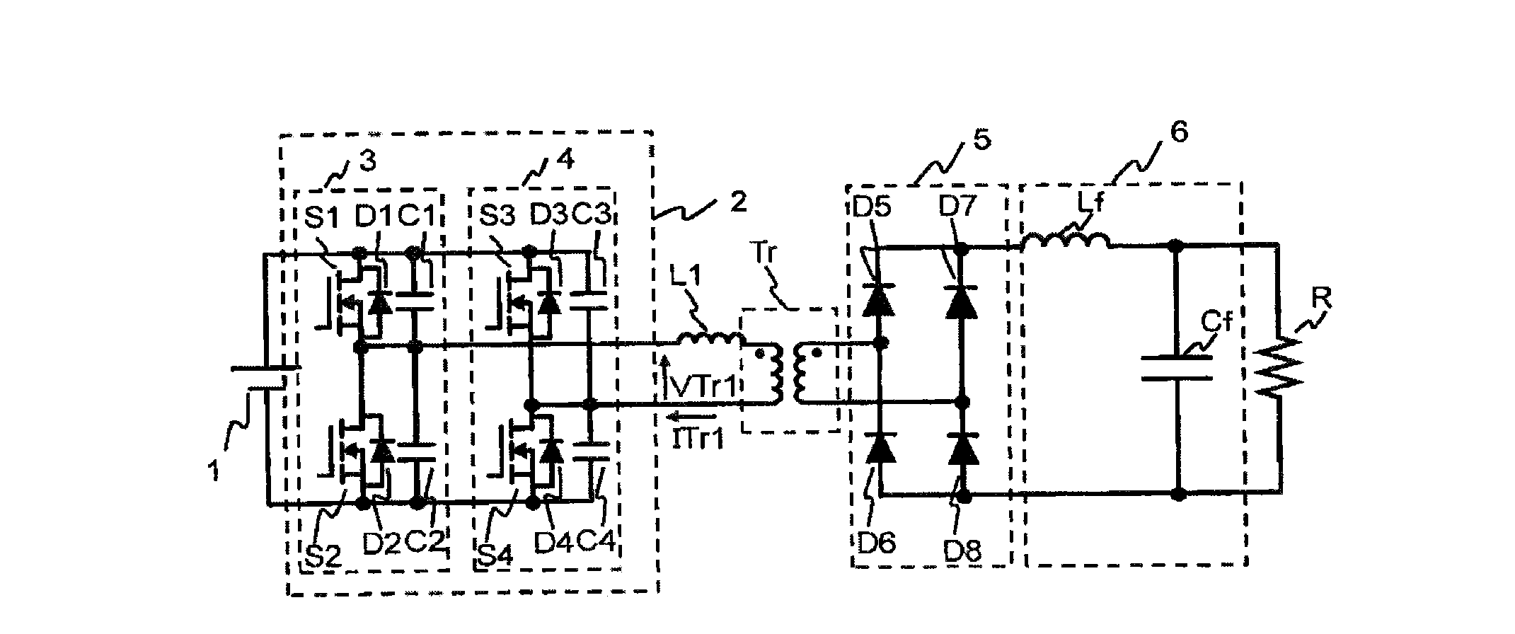
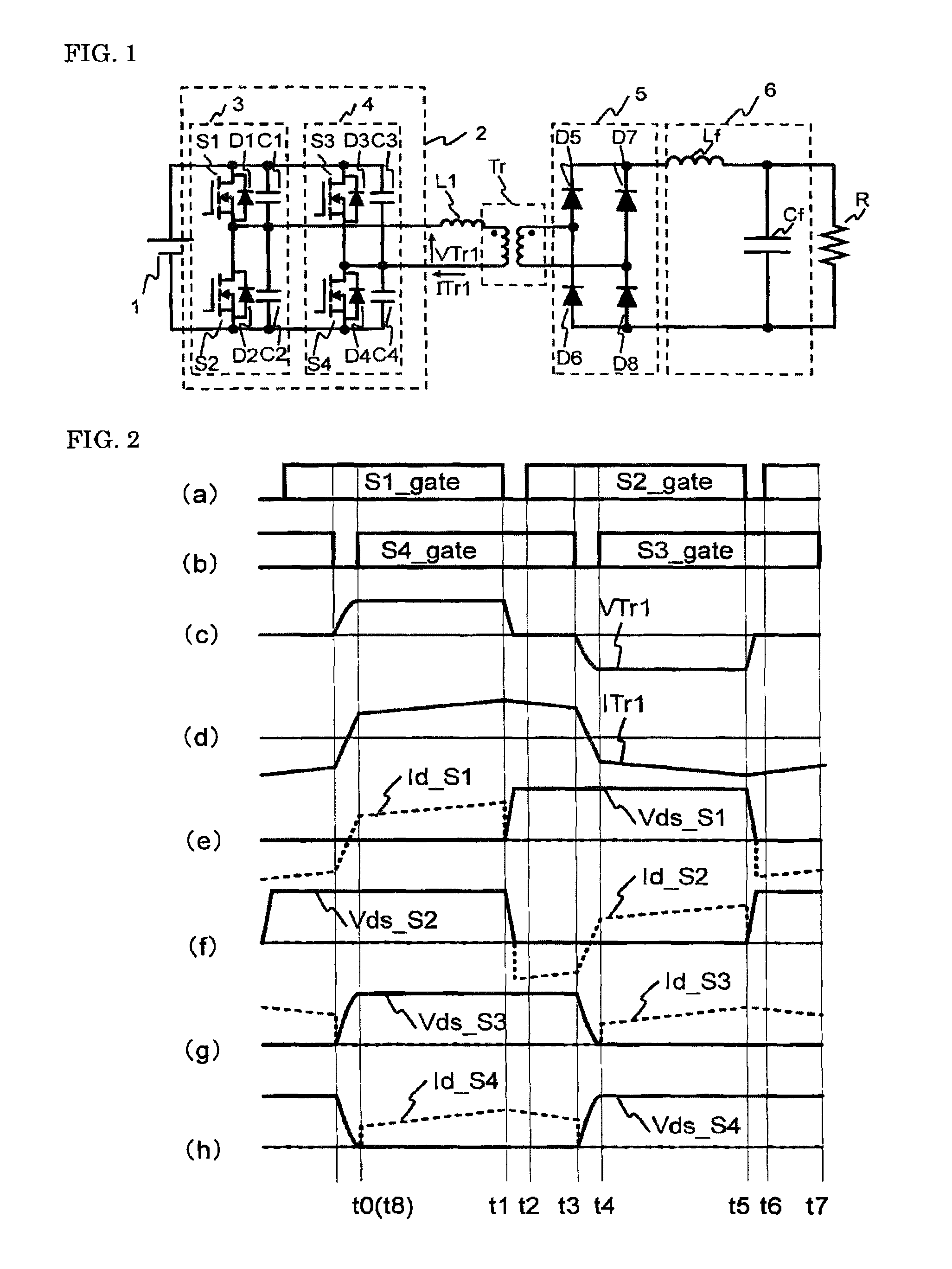
[0023]To begin with, a primary-side phase-shift type DC-DC converter, underlying the present invention, with a full-bridge inverter and a rectifier circuit combined together will be explained referring to FIG. 1 and FIG. 2.
[0024]In FIG. 1, the full-bridge inverter 2 (hereinafter simply referred to as an inverter) converts a DC voltage from a DC power supply 1 into a high-frequency AC voltage and inputs the voltage to a transformer Tr. A rectifier circuit 5 rectifies the high-frequency AC voltage output from the transformer Tr. An output smoothing filter 6 constituted of a smoothing reactor (choke coil) Lf and a smoothing capacitor Cf removes high-frequency components from the voltage output from the rectifier circuit 5, and the resultant DC voltage is supplied to a load R.
[0025]The full-bridge inverter 2 comprises a circuit constituted of a reference phase ...
embodiment 2
[0070]A DC-DC converter according to Embodiment 2 of the present invention will be explained based on FIG. 5.
[0071]Additionally, it is assumed that the circuit configuration is the same as that in FIG. 1 and MOSFETs are used for the switching elements constituting the full-bridge inverter 2.
[0072]Moreover, (a) to (h) in FIG. 5 show driving signals supplied to the switching elements S1 to S4, the voltage VTr1 input to the transformer Tr, the current ITr1 flowing through the primary coil of the transformer, voltages across the switching elements S1 to S4: Vds-S1 to Vds-S4 (solid lines), and Id-S1 to Id-S4 flowing through S1 to S4 (broken lines), respectively.
[0073]Furthermore, time t0 to time t6 represents switching times of the switching elements S1 to S4; Vds, a drain voltage of each switching element with respect to a source voltage thereof; and Id, a current through each switching element, with the direction flowing therein from the drain positive. Additionally, in FIG. 5, the per...
embodiment 3
[0087]A DC-DC converter according to Embodiment 3 of the present invention will be explained based on FIG. 6.
[0088]Additionally, it is assumed that the circuit configuration is the same as that in FIG. 1 and MOSFETs are used for the switching elements constituting the full-bridge inverter 2.
[0089]Moreover, (a) to (h) in FIG. 6 show driving signals supplied to the switching elements S1 to S4, the voltage VTr1 input to the transformer, the current ITr1 flowing through the primary coil of the transformer, voltages across the switching elements S1 to S4: Vds-S1 to Vds-S4 (solid lines), and Id-S1 to Id-S4 flowing through S1 to S4 (broken lines), respectively.
[0090]Furthermore, time t0 to t6 represents switching times of the switching elements S1 to S4; Vds, a drain voltage of each switching element with respect to a source voltage thereof; and Id, a current through each switching element, with the direction flowing therein from the drain positive. Additionally, in FIG. 6, the period from...
PUM
 Abstract
Description
Claims
Application Information
 - R&D
- Intellectual Property
- Life Sciences
- Materials
- Tech Scout
- Unparalleled Data Quality
- Higher Quality Content
- 60% Fewer Hallucinations
Browse by: Latest US Patents, China's latest patents, Technical Efficacy Thesaurus, Application Domain, Technology Topic, Popular Technical Reports.
© 2025 PatSnap. All rights reserved.Legal|Privacy policy|Modern Slavery Act Transparency Statement|Sitemap|About US| Contact US: help@patsnap.com


