
Overload safety apparatus for robot hand

a safety apparatus and robot hand technology, applied in the field of safety apparatus, can solve the problems of high cost and time, low flexibility of safety apparatus in the related art, and high cost of obtaining high flexibility, so as to reduce size, weight and cost, and simplify the structure

Inactive Publication Date: 2012-02-28
RESONAC HOLDINGS CORPORATION
View PDF2 Cites 2 Cited by
  • Summary
  • Abstract
  • Description
  • Claims
  • Application Information

AI Technical Summary

Benefits of technology

[0007]The present invention provides an overload safety apparatus which is reduced in size, weight and cost, and functions effectively to protect against an overload exerted to the robot hand.
[0014]According to the overload safety apparatus for a robot hand, an effective function to protect against overload exerted to the robot hand in the lateral direction, the vertical direction or the fore-and-aft direction is achieved by a configuration reduced in size, weight and cost in a simplified structure in which the first and second mounting bearing plates are magnetically attracted to each other and supported by the shaft.

Problems solved by technology

The safety apparatus in the related art has low flexibility since the range and direction of displacement of the robot hand is limited, and it is expensive to obtain high flexibility because upsizing and increase in weight of a link mechanism or the like are inevitable.
When an overload exceeding a movable range is exerted to the robot hand, collision or damage of members results, and the robot body is subjected to serious damage, so that there arises a problem that excessive cost and time are required for the maintenance thereof.

Method used


Image

  • Overload safety apparatus for robot hand
  • Overload safety apparatus for robot hand
  • Overload safety apparatus for robot hand

Examples


Embodiment Construction

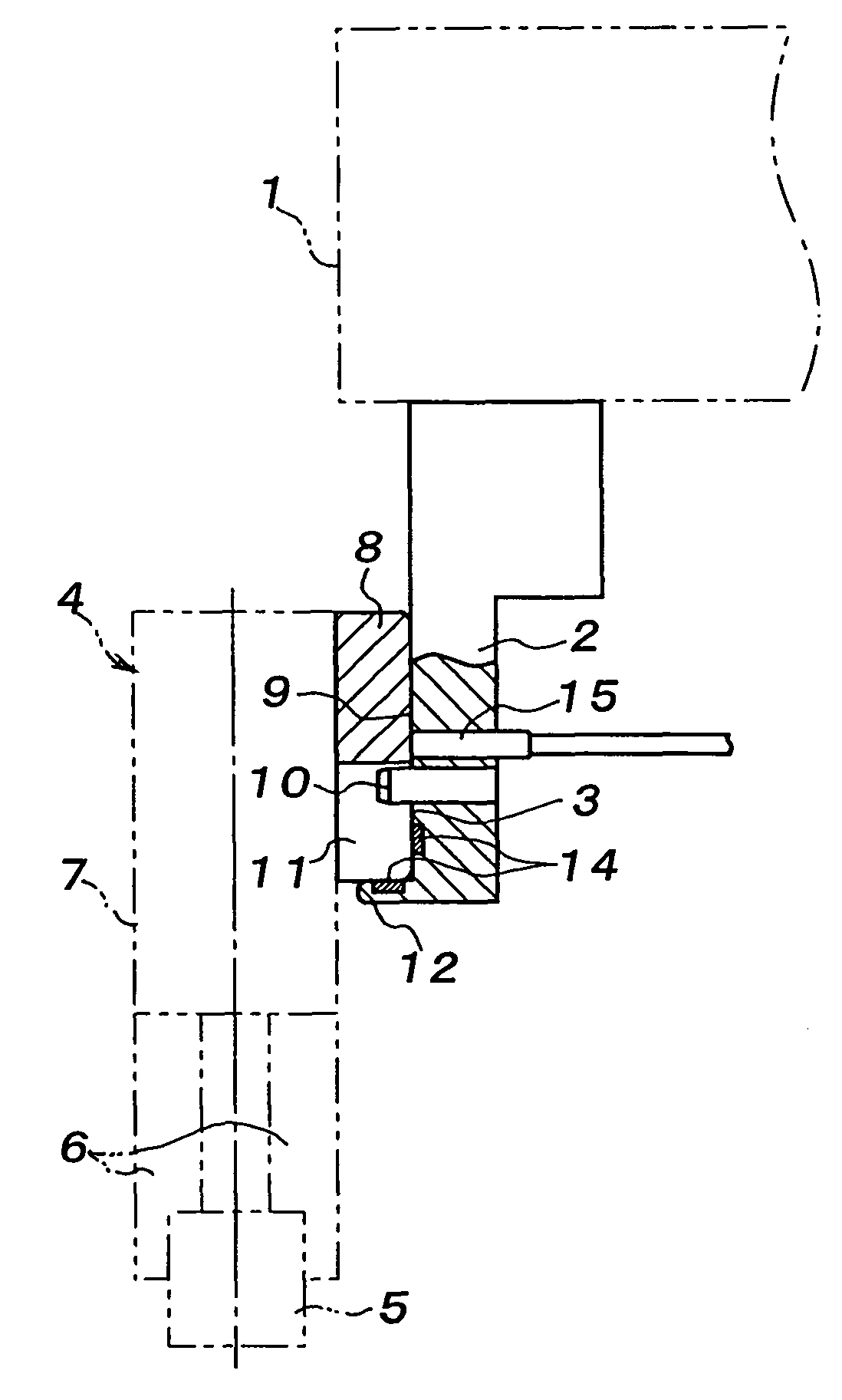
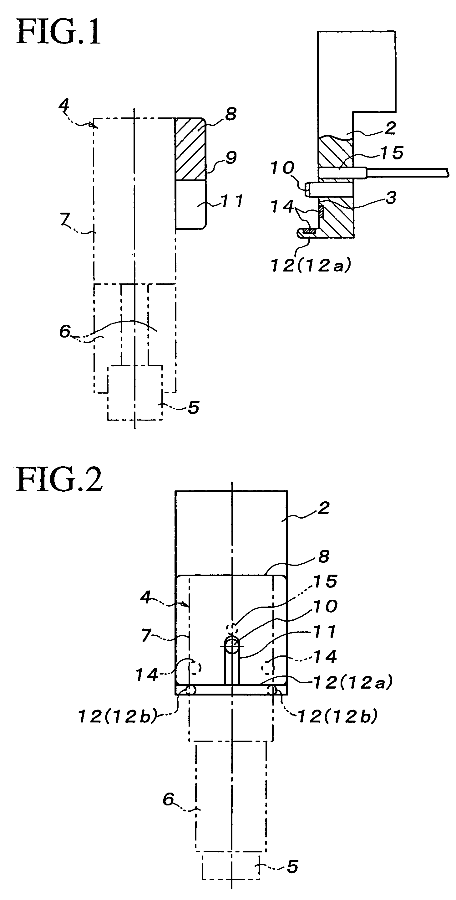
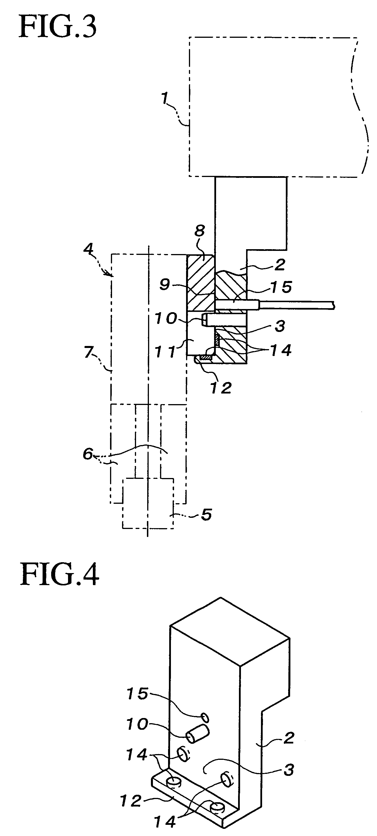
[0025]Referring now to FIG. 1 to FIG. 10, a best mode for carrying out the present invention will be described.

[0026]As shown in FIG. 1 to FIG. 3, a first mounting bearing plate 2 is provided on an arm 1 of a robot body, for example, by attaching in the vertical direction, and the front surface of the first mounting bearing plate 2 is provided as a first magnetically attracting beating face 3.

[0027]On the other hand, a robot hand 4 includes a drive unit 7 having a drive mechanism for an end effecter 6 represented by a chuck integrated therein, and the end effecter 6 extending from the drive unit 7, for example, downward, and acts on a work piece 5 by, for example, opening and closing the end effecter 6 by the drive unit 7.

[0028]A second mounting bearing plate 8 is integrally provided on the rear surface of the drive unit 7 of the robot hand 4, and the front surface of the second mounting bearing plate 8 is provided as a second magnetically attracting bearing face 9.

[0029]The second ...


PUM


Abstract

In a robot hand overload safety apparatus, a first magnetically attracting bearing face 3 is provided at a robot hand mounting portion, and a second magnetically attracting bearing face 9 is provided on the robot hand 4, so that the second magnetically attracting bearing face 9 is magnetically attracted by the first magnetically attracting bearing face 3 and the robot hand 4 is mounted and supported, and in which a shaft 10 projecting from the first or second magnetically attracting bearing face 3, 9 is fitted into a hole or groove 11 opening on the other bearing face, so that the robot hand 4 rotates in the lateral direction, moves in the vertical direction or inclines in the fore-and-aft direction against the magnetically attracting force via the fitting between the shaft and the hole or groove 11 due to an overload exerted to the robot hand 4.

Description

BACKGROUND OF THE INVENTION[0001]1. Field of the Invention[0002]The present invention relates to a safety apparatus to protect against an overload exerted to a robot hand of a robot.[0003]2. Related Art[0004]In an overload safety apparatus according to the related art, a robot hand and a mounting portion thereof are joined so as to be capable of moving via a link mechanism or the like, the displacement of the robot hand due to the overload is detected by a sensor, and a robot body is stopped by the detection signal, so that the robot hand and the robot body are protected from the overload.SUMMARY OF THE. INVENTION[0005]The safety apparatus in the related art has low flexibility since the range and direction of displacement of the robot hand is limited, and it is expensive to obtain high flexibility because upsizing and increase in weight of a link mechanism or the like are inevitable.[0006]When an overload exceeding a movable range is exerted to the robot hand, collision or damage o...

Claims


Application Information

Patent Timeline
Patent Type & Authority Patents(United States)
IPC IPC(8): B25J17/00
CPCB25J19/063Y10T74/20329Y10T74/20335
Inventor YANAI, KATSUYAURUSHIBARA, FUMIO
Owner RESONAC HOLDINGS CORPORATION
Learn More