
Flood control devices and methods

Active Publication Date: 2017-02-07
A WALL LLC
View PDF27 Cites 17 Cited by
  • Summary
  • Abstract
  • Description
  • Claims
  • Application Information

AI Technical Summary

Benefits of technology

The present invention relates to a water or flood control device or method of making, assembling, or using the device. The invention aims to provide an alternative to the slow and labor-intensive use of sandbags, which are commonly used to control floods. The invention offers a faster and more efficient way to deploy flood control devices and methods. The invention includes various triangular shaped support structures, braces, and frames that can be used to support and reinforce flood control devices. The invention also includes a shaped sheet of material with flaps that can be wrapped around or stacked on top of each other. The technical effects of the invention include reducing the effects of floods and preventing damage to human life and property.

Problems solved by technology

As one example, runoff from sustained or heavy rainfall, or rapid snow melt, may cause the water level in a river to rise until it exceeds the capacity of the rivers channel, which may cause a flood.
As another example, an obstruction, such as, for example, ice or a landslide, may obstruct a river channel, which may cause flooding upstream of the obstruction.
As yet another example, a flood may occur when a levy or dike is damaged.
Such floods, especially when they occur in populated areas, are generally undesirable.
The floods may cause significant damage to homes, businesses, vehicles, farms, and the like.
In addition, in severe cases, the floods may place human life at risk.
However, one potential drawback with the use of sandbags is that the sandbags tend to be relatively slow and labor intensive to deploy.
Each bag generally needs to be filled with sand or soil on site, which may take a significant amount of time.

Method used


Image

  • Flood control devices and methods
  • Flood control devices and methods
  • Flood control devices and methods

Examples


Embodiment Construction

[0026]In the following description, numerous specific details are set forth. However, it is understood that embodiments of the invention may be practiced without these specific details. In other instances, well-known structures and techniques have not been shown in detail in order not to obscure the understanding of this description.

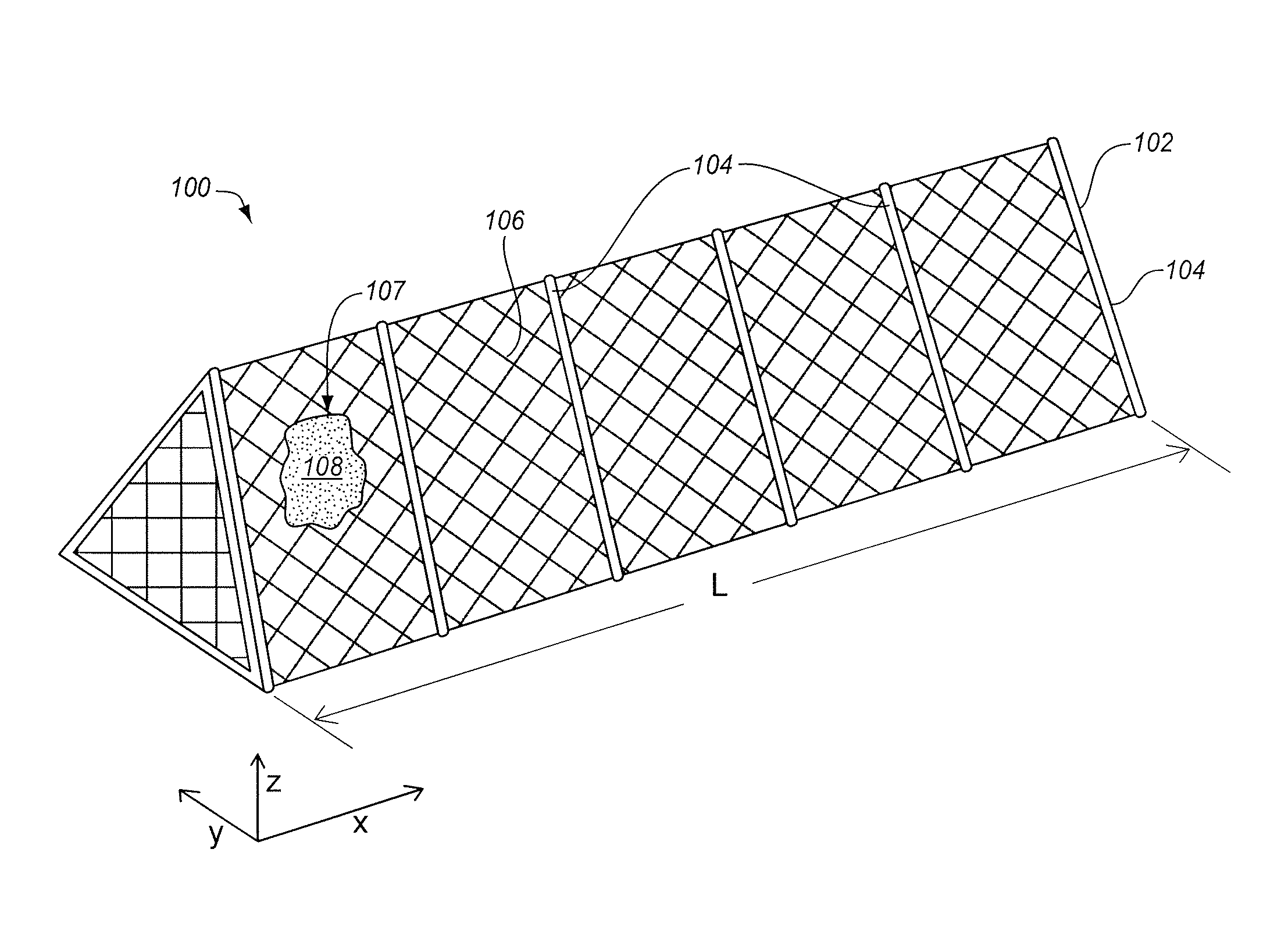
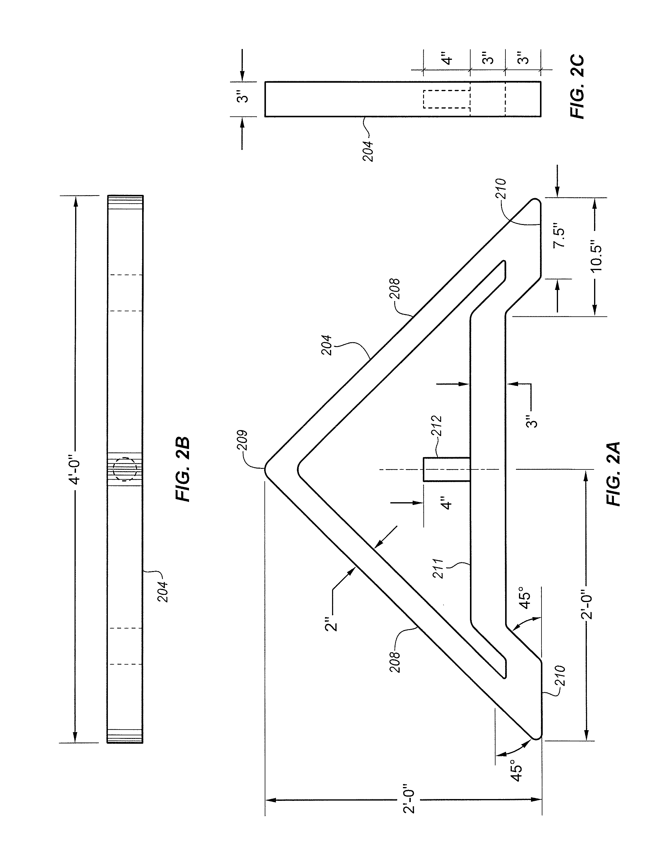
[0027]Embodiments of flood control apparatus, methods, and kits are disclosed herein. Commonly an embodiment of a flood control apparatus may include a structural frame having an elongated length in a given direction. Commonly, the structural frame may be capable of being coupled together to form an elongated length of at least 100 feet. Commonly, a width of the apparatus or structural frame is at least 2 feet, or longer. Commonly, a height of the apparatus or structural frame is 2 feet, or higher. One or more sheets of material may be coupled around the structural frame. A hollow or void inner region may exist within the one or more sheets of material t...


PUM


Abstract

Flood control apparatus are disclosed. In one aspect, a flood control apparatus includes a structural frame. The structural frame has an elongated length in a longitudinal direction. The structural frame includes a plurality of transverse support structures, that are generally aligned in the transverse direction, and that are spaced apart in the longitudinal direction. The structural frame includes one or more longitudinal coupling structures that couple the plurality of transverse support structures together. One or more sheets of material are coupled to the structural frame. When in use, earth may be used to substantially fill an inner region of the apparatus that is enclosed by the one or more sheets of material coupled to the structural frame.

Description

RELATED APPLICATIONS[0001]The present application claims priority from U.S. Provisional Patent Application Ser. No. 61 / 180,036, entitled “FLOOD CONTROL DEVICES AND METHODS,” filed on May 20, 2009, by Abron J. Arrington. U.S. Provisional Patent Application Ser. No. 61 / 180,036 is hereby incorporated herein by this reference.BACKGROUND[0002]Field[0003]Embodiments of the invention relate to a water or flood control device, or method of making, assembling, or using the water or flood control devices, or a kit therefor.[0004]Background Information[0005]A flood generally refers to an overflow of water from a river, lake, or other body or expanse of water. When the water overflows, it escapes its normal boundaries, and flows onto normally dry land.[0006]There are various causes of floods. As one example, runoff from sustained or heavy rainfall, or rapid snow melt, may cause the water level in a river to rise until it exceeds the capacity of the rivers channel, which may cause a flood. As an...

Claims


Application Information

Patent Timeline
IPC IPC(8): E02B7/14E02B3/10E02B3/04
CPCE02B3/106E02B3/04E02B3/108
Inventor ARRINGTON, ABRON J.
Owner A WALL LLC
Learn More