Eureka AIR delivers breakthrough ideas for toughest innovation challenges, trusted by R&D personnel around the world.

Tool gravity center position estimation device and machine tool

a technology of center position estimation and tool, which is applied in the direction of manufacturing tools, metal-working machine components, instruments, etc., can solve the problems of inability to accurately estimate the impact on the machine or the load on the motor only with the information of the tool weight, and the difficulty of using the gravity center position information of the tool

Active Publication Date: 2017-01-31
FANUC LTD
View PDF14 Cites 0 Cited by
  • Summary
  • Abstract
  • Description
  • Claims
  • Application Information

AI Technical Summary

Benefits of technology

[0015]The shape data value in the tool shape model is calculated based on the tool moment of inertia and tool weight to thereby estimate a tool shape from the shape data value, and the gravity center position of the tool is calculated based on the estimated tool shape. As a result, an impact applied to a machine tool at its operation time can be estimated more accurately than in the case where it is estimated only from the tool weight data.
[0033]By notifying, upon estimation of the tool shape, a user of a change from the previously estimated tool shape stored in the data storage unit, it is possible to make the user confirm whether the tool is changed or not and to inform the user of occurrence of any abnormality in the tool or machine tool.

Problems solved by technology

A device that changes an operating speed of a machine according to a tool weight, like the tool changer disclosed in JP 11-188557 A, can be driven while suppressing an impact on the machine or heat generation from a motor; however, sometimes the impact on the machine or a load on the motor cannot be estimated accurately only with information of the tool weight.
Further, the devices disclosed in respective JP 05-138502 A and JP 2013-186545 A can control the operating speed of a motor for the spindle by calculating the moment of inertia of the spindle; however, also in this configuration, sometimes the impact on the machine or a load on the motor cannot be estimated accurately only with information of the moment of inertia of the spindle.
However, it is troublesome for a user to measure or calculate the gravity center position of each tool in advance, which may make it difficult to use the gravity center position information of the tool so as to perform appropriate operation setting of the machine tool.

Method used


Image

  • Tool gravity center position estimation device and machine tool
  • Tool gravity center position estimation device and machine tool
  • Tool gravity center position estimation device and machine tool

Examples


Embodiment Construction

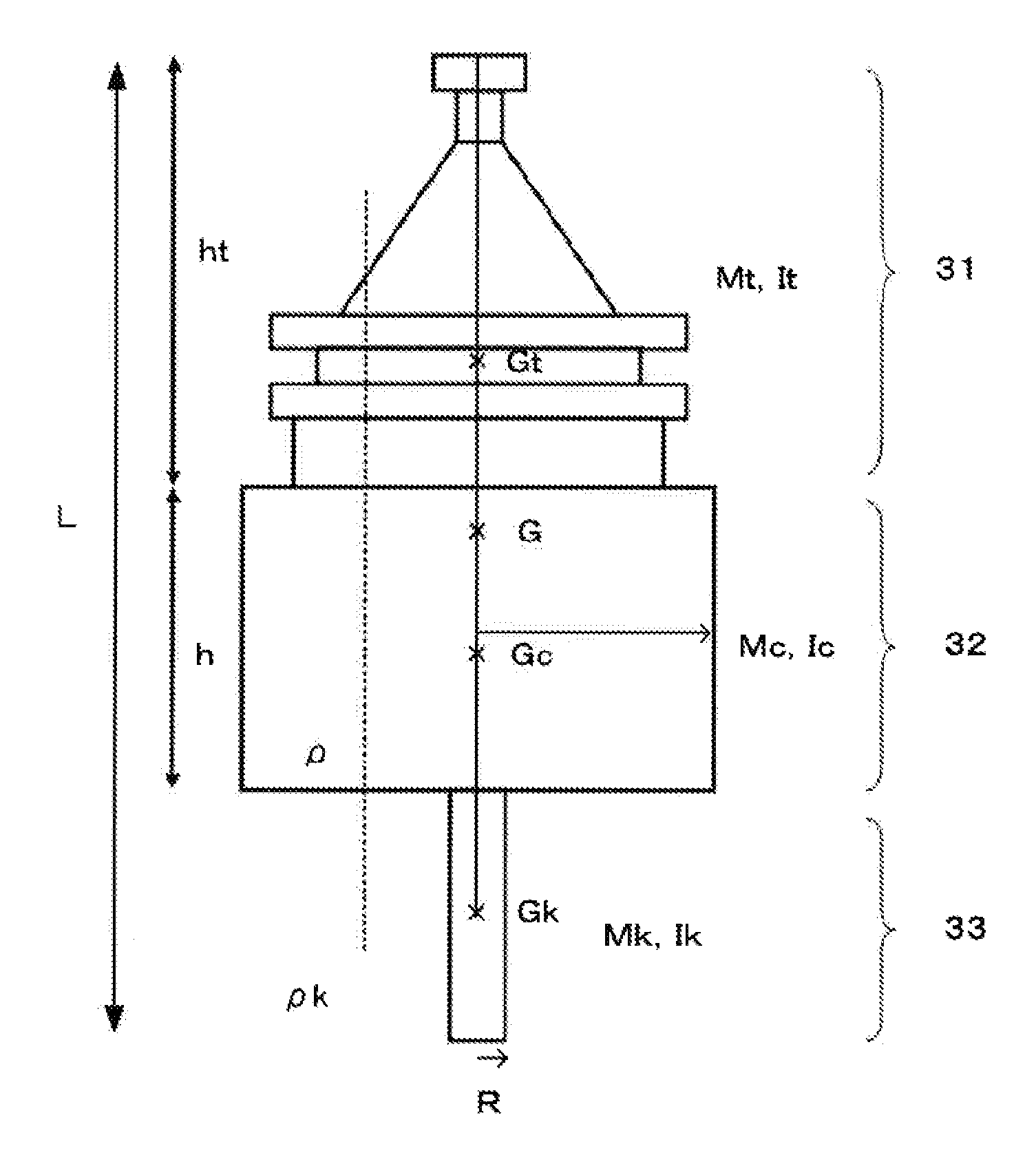
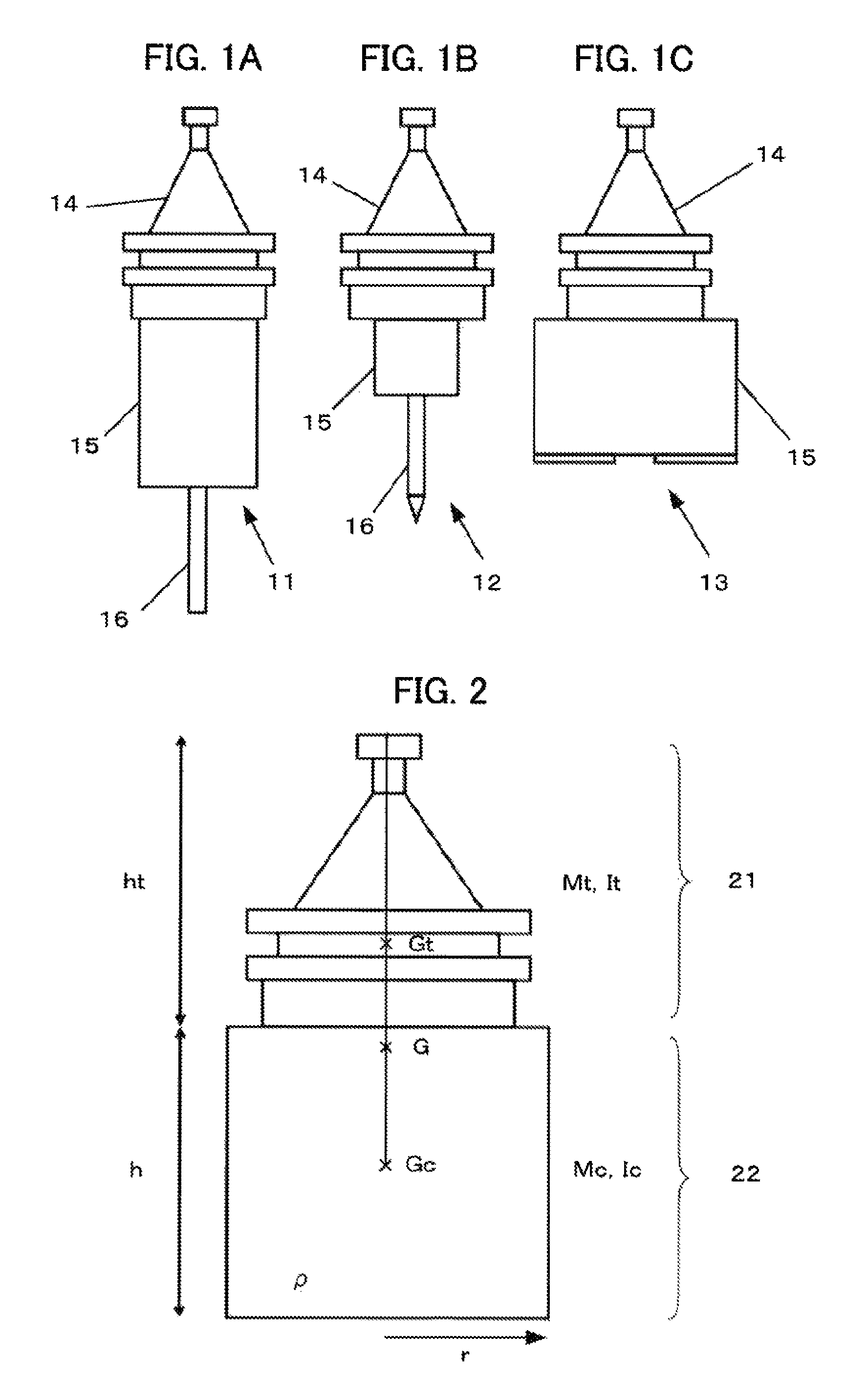
[0041]First, a method of estimating a shape of a tool based on moment of inertia and a weight of the tool and then calculating a gravity center position will be described. FIGS. 1A to 1C are views schematically illustrating some types of tools. FIG. 1A illustrates a milling tool 11, FIG. 1B is a drilling tool 12, and FIG. 1C illustrates a milling cutter tool 13. The above tools 11 to 13 have tool holder portions 14 having substantially the same shape. Further, the milling tool 11 and drilling tool 12 each have, at their leading ends, a blade portion 16.

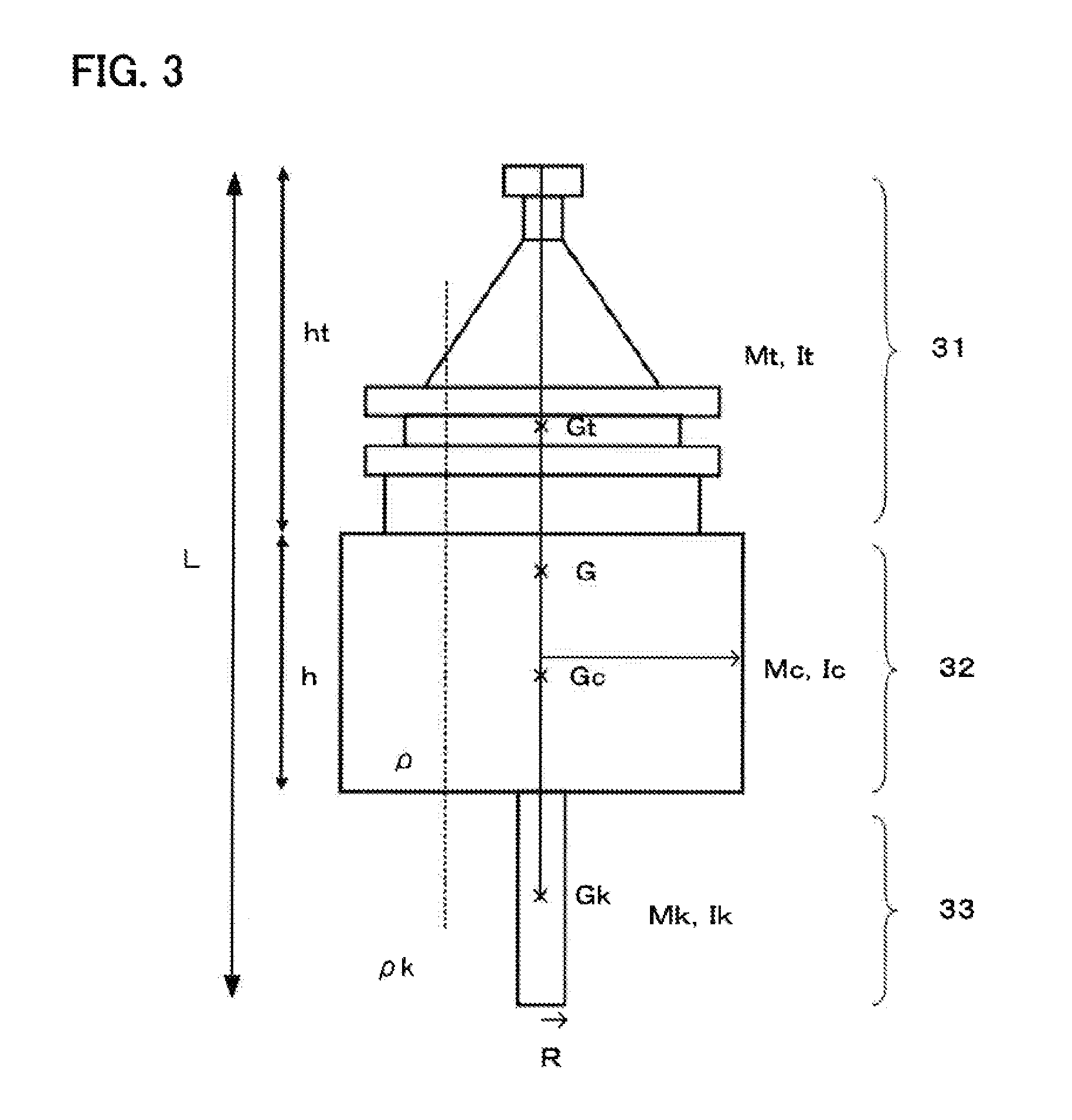
[0042]Although a part (i.e.,) to be fitted to the tool holder portion 14 differs in height or width depending on a type of the tool, a portion to be fitted with the blade portion 16 in the tools 11, 12 and the tool 13 itself generally has a substantially columnar shape. Hereinafter, the portion having the substantially columnar shape is referred to as “columnar portion 15”. The blade portion 16 in the milling tool 11 and drilling tool...


PUM


Abstract

A value of shape data is calculated from moment of inertia and weight data of a tool, a relational expression between shape data and tool moment of inertia in a predetermined tool shape model, and a relational expression between the shape data and tool weight in the tool shape model to estimate a shape of the tool, and a gravity center position of the tool is calculated based on the estimated tool shape.

Description

RELATED APPLICATIONS[0001]The present application claims priority to Japanese Application Number 2013-272509, filed Dec. 27, 2013, the disclosure of which is hereby incorporated by reference herein in its entirety.BACKGROUND OF THE INVENTION[0002]Field of the Invention[0003]The present invention relates to a tool gravity center position estimation device that estimates a gravity center position of a tool and a machine tool using the estimated tool gravity center position.[0004]Description of the Related Art[0005]Conventionally, there is known a machine tool having a function of changing an operating speed of a tool changer according to a weight of an attached tool. Such a machine tool uses this function to operate the tool changer at an optimum speed, which allows the machine tool to be driven at a sufficient speed while suppressing an impact on the machine or heat generation from a motor.[0006]Further, there is known a machine tool having a function of estimating moment of inertia ...

Claims


Application Information

Patent Timeline
Patent Type & Authority Patents(United States)
IPC IPC(8): G06F17/50
CPCG06F17/50B23Q3/15546G06F30/00G06F30/17
Inventor MUROTA, MASAHIROISOBE, GAKU
Owner FANUC LTD
Why Eureka
Eureka Blog
Learn More