Eureka AIR delivers breakthrough ideas for toughest innovation challenges, trusted by R&D personnel around the world.

Orthopedic anchoring system and methods

a technology of orthopedic anchoring and orthopaedic bone, which is applied in the field of orthopaedic bone anchoring systems and methods, can solve the problems of insufficient engagement of existing implant structures with the articular surfaces or cortical bone of the joint for adequate fixation or fusion, failure to relieve the condition being treated, and loosening of existing pedicle screws and/or implants, etc., to achieve the effect of reducing the risk of fracture, reducing the risk of reducing

Active Publication Date: 2017-01-31
JCBD
View PDF464 Cites 40 Cited by
  • Summary
  • Abstract
  • Description
  • Claims
  • Application Information

AI Technical Summary

Problems solved by technology

One limitation of many existing fusion procedures involves the challenge of situating a fusion implant in suitably close alignment with the removed tissues of the patient to achieve a stable fixation of the joint or vertebrae.
Existing implant structures may have insufficient engagement with the articular surfaces or cortical bone of the joint for adequate fixation or fusion.
This failure to sufficiently stabilize and fuse the joint with the conventional implant structures and methods may result in a failure to relieve the condition being treated.
Existing pedicle screws and / or implants may loosen, back out, or otherwise functionally degrade due to the cumulative effect of forces and torques experienced as a result of normal posture and / or movements including bending, sitting, walking, and any other typical movements.

Method used


Image

  • Orthopedic anchoring system and methods
  • Orthopedic anchoring system and methods
  • Orthopedic anchoring system and methods

Examples


Embodiment Construction

[0100]Disclosed herein is an orthopedic anchoring system and method for providing structural support, reinforcement, and / or anchoring for a variety of orthopedic appliances. Non-limiting examples of orthopedic devices compatible with aspects of the orthopedic anchoring system include: vertebral reinforcement or immobilization devices; intervertebral joint reinforcement or immobilization devices; internal fixation devices; and any other orthopedic appliances or orthopedic applications known in the art.

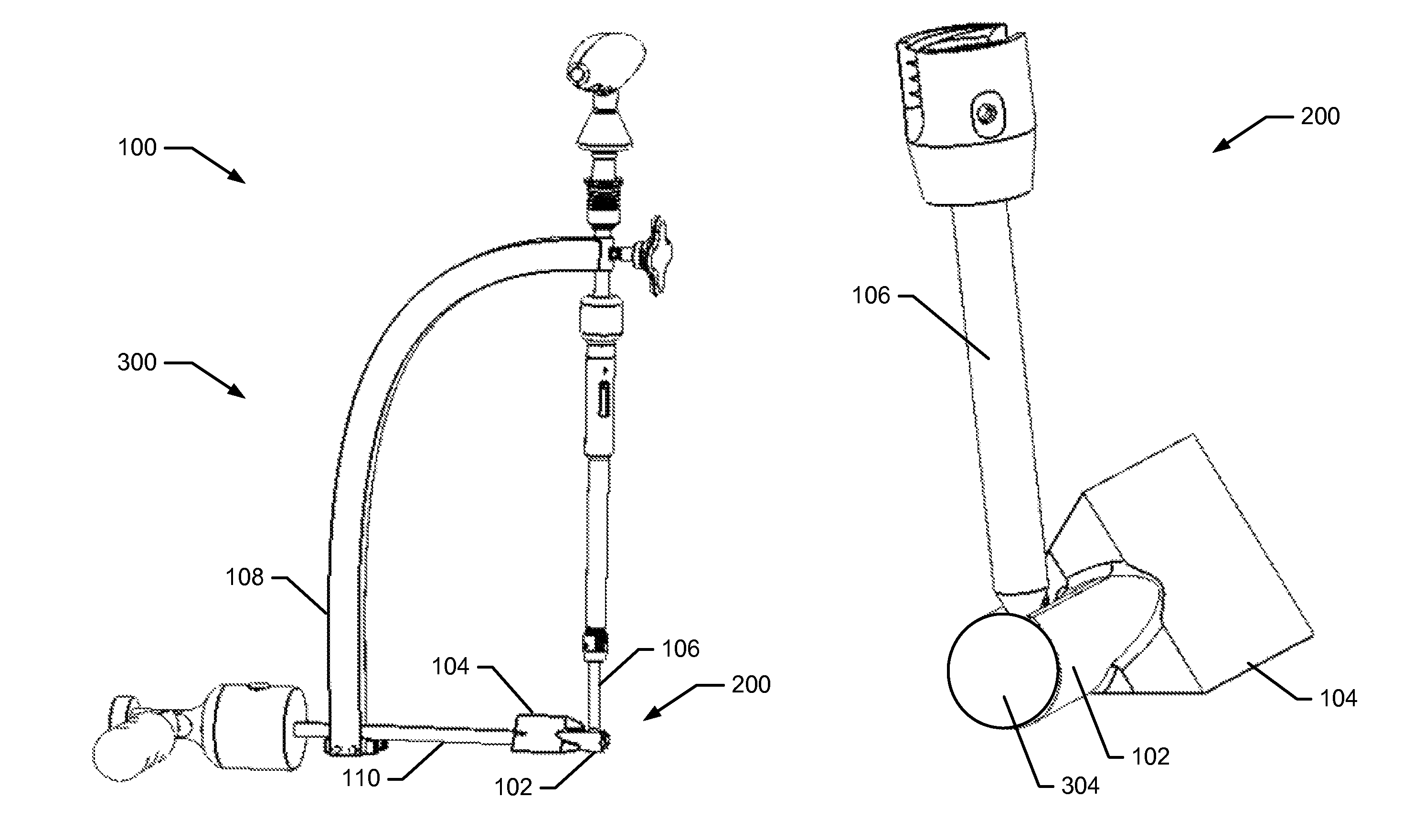
[0101]A side view of the elements of an orthopedic anchoring system 100 is illustrated in FIG. 1. In an aspect, the system 100 includes an implant assembly 200 and a delivery tool 300. The implant assembly 200 may be situated and installed within a selected afflicted region of a patient, such as an intervertebral joint, using the delivery tool 300. In an aspect, the implant assembly 200 may include an implant body 102, an implant outer layer 104 and a fastener 106. The implant assembly ...


PUM


Abstract

Systems and methods for performing orthopedic surgical procedures to treat a patient are presented herein. The orthopedic anchoring system may include an implant assembly and a delivery tool to perform the orthopedic surgical procedure. The implant assembly may include an implant outer layer, an implant body situated within the implant outer layer, and a fastener attached to a locking element of the implant body. The delivery tool may include a targeting arm, a fastener guide removably attached at a first end of the targeting arm and an implant guide removably attached to a second end of the targeting arm. The delivery tool may maintain a fixed spatial relationship between a longitudinal axis of the fastener and a longitudinal axis of the implant outer layer and implant body. The orthopedic anchoring system may be used to perform orthopedic surgical procedures related to joint reinforcement or immobilization.

Description

CROSS REFERENCE TO RELATED APPLICATIONS[0001]This application claims priority to U.S. Provisional Application No. 61 / 798,922 filed Mar. 15, 2013, which is entitled “Orthopedic Anchoring System and Methods”, and also claims priority to U.S. Provisional Application No. 61 / 674,233, which is entitled “Orthopedic Anchoring System and Methods” filed Jul. 20, 2012.[0002]All of the aforementioned applications are hereby incorporated by reference in their entireties into the present application.FIELD OF THE INVENTION[0003]Aspects of the present invention relate to systems and methods related to a medical apparatus. More specifically, the present invention relates to devices and methods for joint, vertebral or intervertebral joint reinforcement or immobilization.BACKGROUND OF THE INVENTION[0004]Reinforcement, stabilization, or fusion of a joint or vertebrae may be indicated as a treatment of an afflicted region of a patient. Examples of specific treatments include spinal stabilization, spinal...

Claims


Application Information

Patent Timeline
Patent Type & Authority Patents(United States)
IPC IPC(8): A61F2/30A61B17/70A61B17/17A61F2/46A61B17/88A61B17/15
CPCA61F2/30749A61B17/1757A61B17/7055A61B17/7076A61F2/30A61F2/4637A61B17/15A61B17/8875A61F2002/30332A61F2002/30378A61F2002/30495A61F2002/30617A61F2002/4642A61B17/58A61B17/88
Inventor DONNER, EDWARD JEFFREYDONNER, CHRISTOPHER THOMAS
Owner JCBD
Why Eureka
Eureka Blog
Learn More