
Saw blade

a saw blade and blade technology, applied in metal sawing tools, metal sawing equipment, metal-working equipment, etc., can solve the problems of deteriorating working conditions, unidirectional rotation of blades, and high cutting ability of both types of saws,

Active Publication Date: 2017-01-17
C & E FEIN GMBH & CO KG
View PDF13 Cites 0 Cited by
  • Summary
  • Abstract
  • Description
  • Claims
  • Application Information

AI Technical Summary

Benefits of technology

This patent describes a saw blade for an electric saw tool that has cutting teeth on the outer edge. The saw blade is designed to have low strength to prevent collisions and may be thinner than traditional blades. The invention also includes a height difference between the cutting teeth at the left and right ends to reduce collisions and heat generation. The saw blade is connected to the saw tool through a coupling part and is suitable for cutting thick wood. The unique design features a elliptical shape and small teeth height difference between the left and right ends, which allows for effective cutting of even thick wood without generating heat or deformation.

Problems solved by technology

Both types of saw have high ability of cutting but do not yet become an ideal tool since they are problematic in safety, scatter loose particles from cutting, make loud noises, and so on.
Strictly speaking, the cutting teeth on the saw blade make a circular movement, but show a spurious situation of linear reciprocating movement due to the quite small swing angle.
However, this cutting is performed through unidirectional rotation of the blade.
Besides, in use of the round saw, the loose particles from cutting jet and scatter at a substantial high initial rate from the slit bore being worked, thereby having a problem of deteriorating the working circumstances.
This can be said to have various problems, such as high dangerousness and so on.
However, there will be inconvenience when making a slit hole in a thick wood.
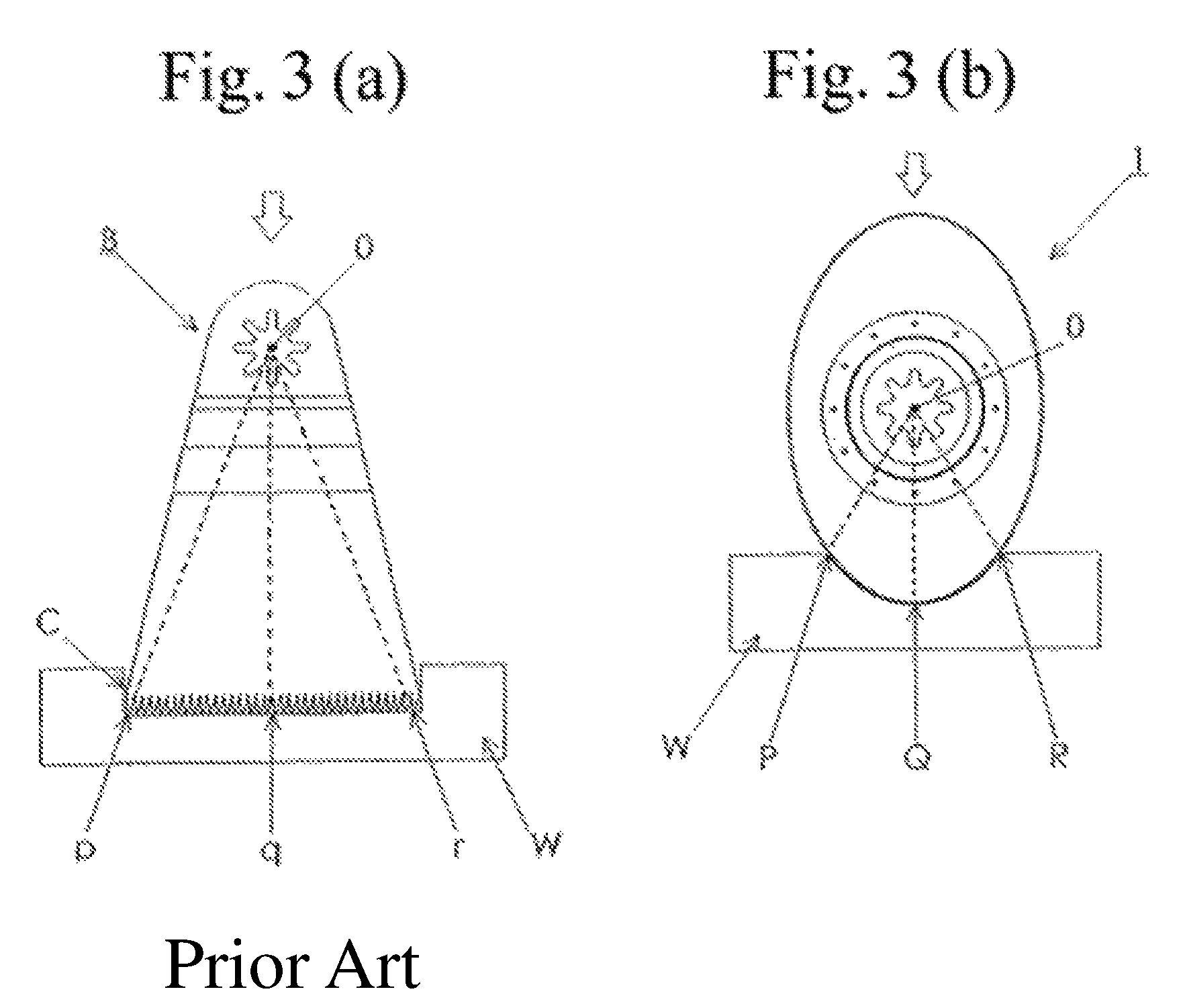
In detail, there is such danger that the saw blade's left side end and right side end continue to collide against left and right lateral sides of the slit hole in the wood to thereby be heated and finally smoke, or, the cutting teeth on the ends of the saw blade are deformed due to heating.
Practically, there has been neither brought onto the market nor proposed any attempts of an improved saw blade structure having no above-mentioned troubles or proposing any improvement for them although generation of heat and deformation was known and seen as a problem.

Method used


Image

  • Saw blade
  • Saw blade
  • Saw blade

Examples


example 1

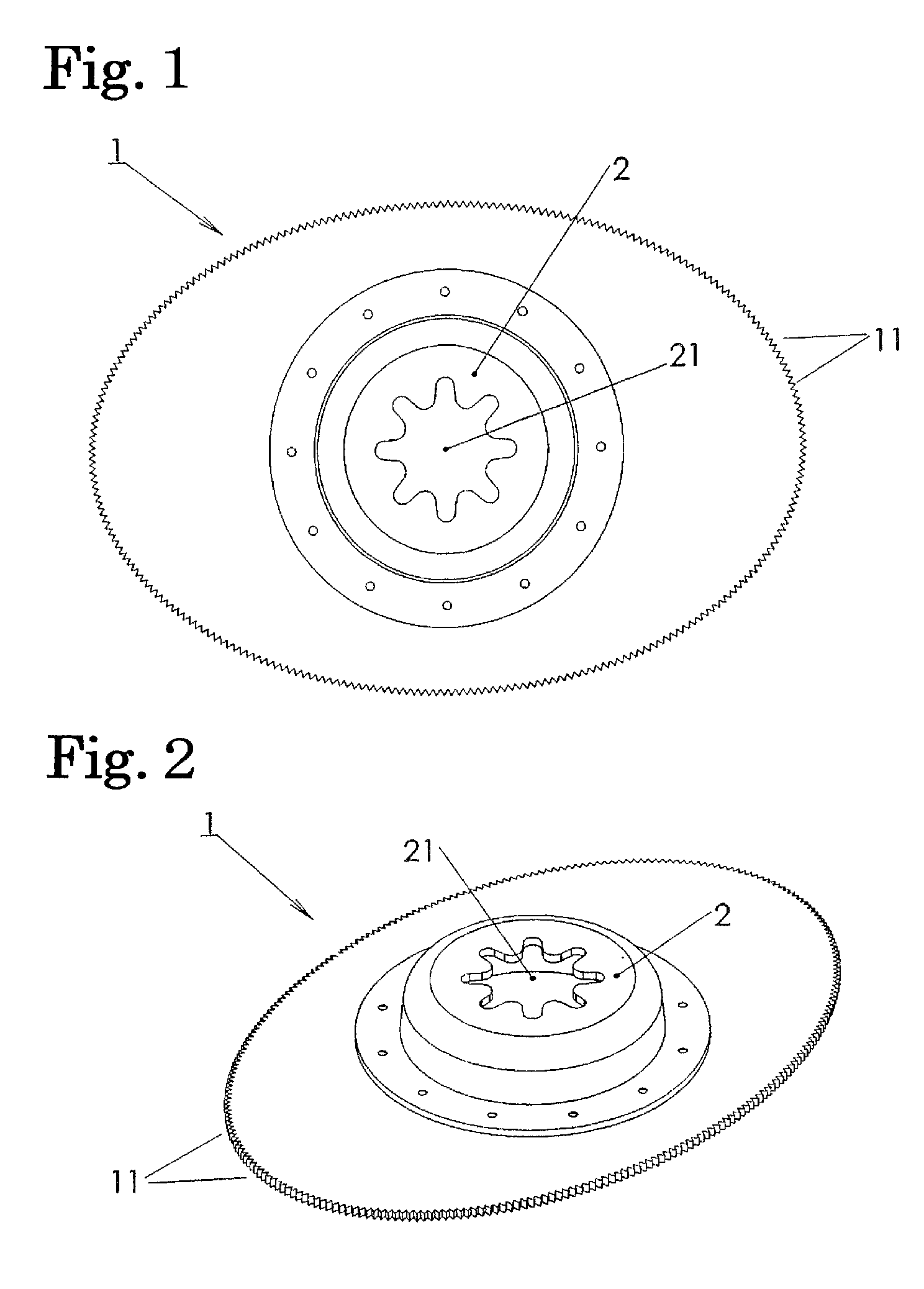
[0034]FIGS. 1 and 2 show an example of a saw blade 1 according to the present invention (called hereunder the saw blade 1), FIG. 1 being a plan view and FIG. 2 a perspective view. As seen from the drawings, the saw blade 1 in this example is generally elliptic in shape.

[0035]The saw blade 1 is a saw blade to be mounted to a tool having a drive shaft of a quality to make an arcuate swing (for example, the tool shown in FIG. 6). The central angle of the arcuate swing in this example is 1.6 degree.

[0036]Cutting teeth 11 are formed on the whole of the elliptic periphery of the saw blade. Teeth 11 are each symmetrically formed at the left and right sides with respect to a line connecting the center of the arcuate swing with crests of the teeth. Thus, there is not caused any difference of the cutting capability in the reciprocation upon the arcuate swing. The number of the cutting teeth 11 is about 250 in this example which is more than twice in comparison with the number of cutting teeth...

example 2

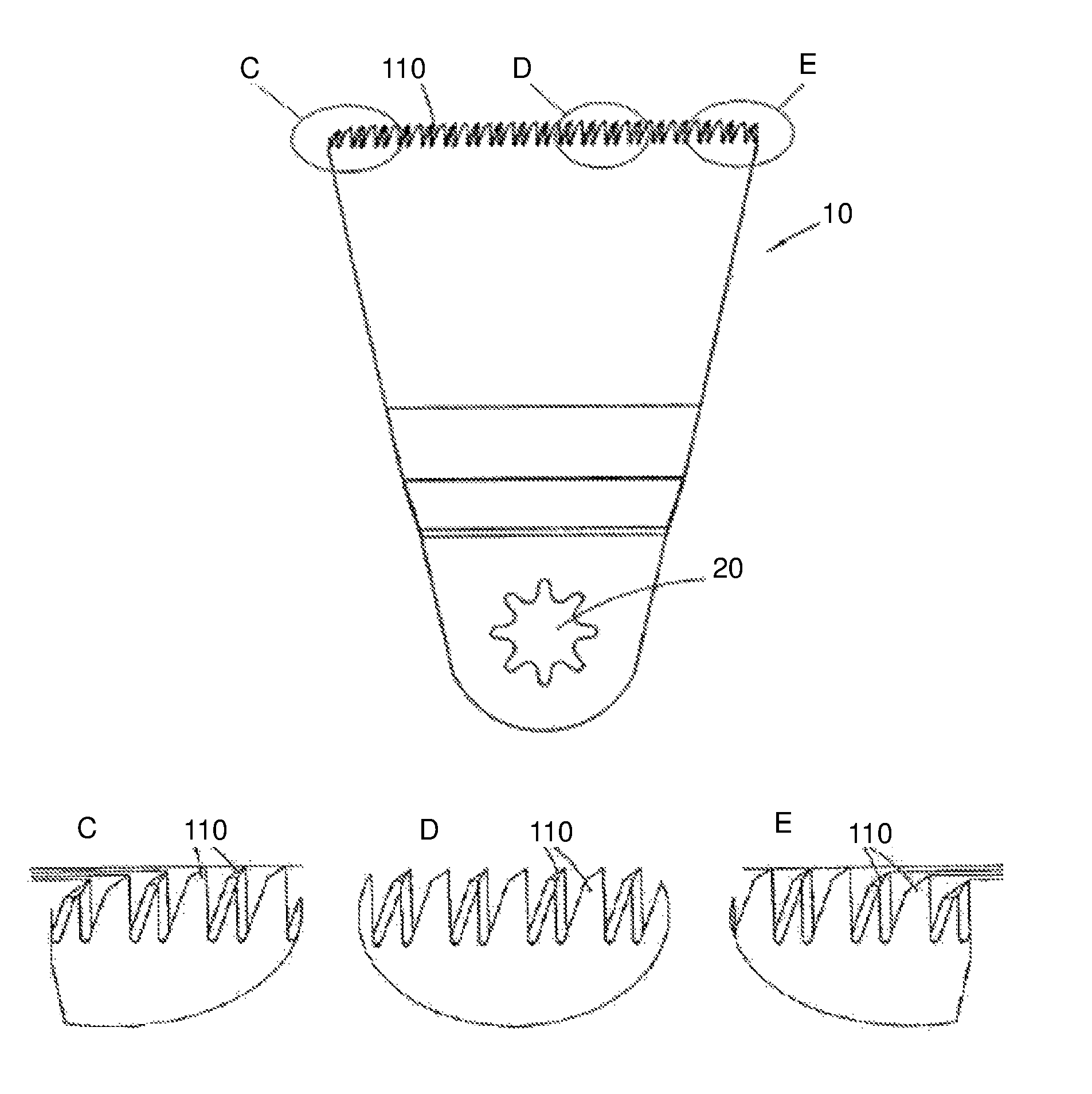
[0048]FIG. 4 is an explanatory view showing another example of a saw blade 10 according to the present invention (called hereunder the saw blade 1), FIG. 4(a) being a schematic plan view and FIG. 4(b) a schematic side view. A saw blade 10 is a saw blade to be mounted to a tool having a drive shaft of a quality to make an arcuate swing (for example, the tool shown in FIG. 6). The saw blade 10 is connected and fixed, at its coupling part 20 to the drive shaft of the tool. Besides, the saw blade 10 is provided with cutting teeth 110 at a remote end opposite to the coupling part 20.

[0049]In this example, the central angle of the arcuate swing is 1.6 degrees.

[0050]The cutting teeth 110 are arranged in a line but are not uniform in height with teeth near and at both ends of the saw blade being smaller in height. FIG. 5 is an enlarged view of the parts C, D, E shown in FIG. 4(a), showing the cutting teeth 110 around the central region (part D) of the saw blade 10, around the right end (par...


PUM

PropertyMeasurementUnit
swing angleaaaaaaaaaa

Abstract

A saw blade for an electric saw tool with a drive shaft making a reciprocating arcuate swing motion, the saw blade comprising a saw plate which has centrally a coupling part for connecting and fixing the saw plate to the drive shaft of the saw tool and has an appearance as being elliptic, and has cutting teeth on the outer periphery. Also, a saw blade for an electric saw tool with a drive shaft making a reciprocating arcuate swing motion, the saw blade having at one end a coupling part for connecting and fixing the saw blade to the drive shaft of the saw tool and having at the other end cutting teeth of the saw blade, and height of the cutting teeth being smaller in the order from near to at both ends of a line of the teeth.

Description

BACKGROUND OF THE INVENTION[0001]Field of the Invention[0002]The present invention relates to a novel structure for a saw blade in such type that the saw blade is mounted and fixed to a drive source, which source performs a reciprocating circular motion (movement) with a small extent of swing amplitude (rotation angle), in order to make cutting.[0003]The terminology “the arcuate swing” referred to hereunder in the specification signifies the aforementioned “reciprocating circular motion with a small extent of swing amplitude (rotation angle)”.[0004]Prior Art[0005]A saw blade is generally categorized in either a type of operation with a reciprocation movement (typically of a manually operable saw) or a type of circular movement (as a round saw). Both types of saw have high ability of cutting but do not yet become an ideal tool since they are problematic in safety, scatter loose particles from cutting, make loud noises, and so on.[0006]Meanwhile, a specific electric cutting tool has b...

Claims


Application Information

Patent Timeline
Patent Type & Authority Patents(United States)
IPC IPC(8): B23D45/16B23D61/00B23D61/12
CPCB23D45/16B23D61/006B23D61/121
Inventor OKADA, TAMOTSU
Owner C & E FEIN GMBH & CO KG
Learn More