
Training apparatus, control segment for training, and control method

a technology for training apparatus and control segment, applied in gymnastics, angiography, catheters, etc., can solve the problems of increasing the burden on muscles and joints, slow-twitch muscle fibers are limited in their potential for growth, and fast-twitch muscle fibers require a significant amount of exercises, so as to reduce the amount of blood flowing, improve the effect of outcom

Active Publication Date: 2017-01-17
KAATSU JAPAN
View PDF14 Cites 2 Cited by
  • Summary
  • Abstract
  • Description
  • Claims
  • Application Information

AI Technical Summary

Benefits of technology

The apparatus ensures safe and effective KAATSU training by determining an appropriate compression force through pulse wave analysis, reducing the risk of excessive arterial occlusion and enhancing muscle development efficiency.

Problems solved by technology

Slow-twitch muscle fibers are limited in their potential for growth.
This recruitment of fast-twitch muscle fibers requires a significant amount of exercises, is time-consuming, and tends to increase the burden on muscles and joints.
Consequently, the muscles get extremely exhausted.
In addition, the muscle fatigue is also caused by the fact that the lactic acid that has built up in the muscles is less likely to be removed from the muscles because of the temporal occlusion of the veins.
More specifically, the KAATSU training method is intended to apply an appropriate compression force upon at least one of the limbs at a predetermined location near the top thereof, for the blood flow restriction into the limb distal to that location; put an appropriate stress attributed to blood flow decrease on the muscles, by the compression force; and thereby cause muscle fatigue.
On the other hand, the KAATSU training can endanger the health of the user if the blood flow is excessively restricted.

Method used


Image

  • Training apparatus, control segment for training, and control method
  • Training apparatus, control segment for training, and control method
  • Training apparatus, control segment for training, and control method

Examples


first embodiment

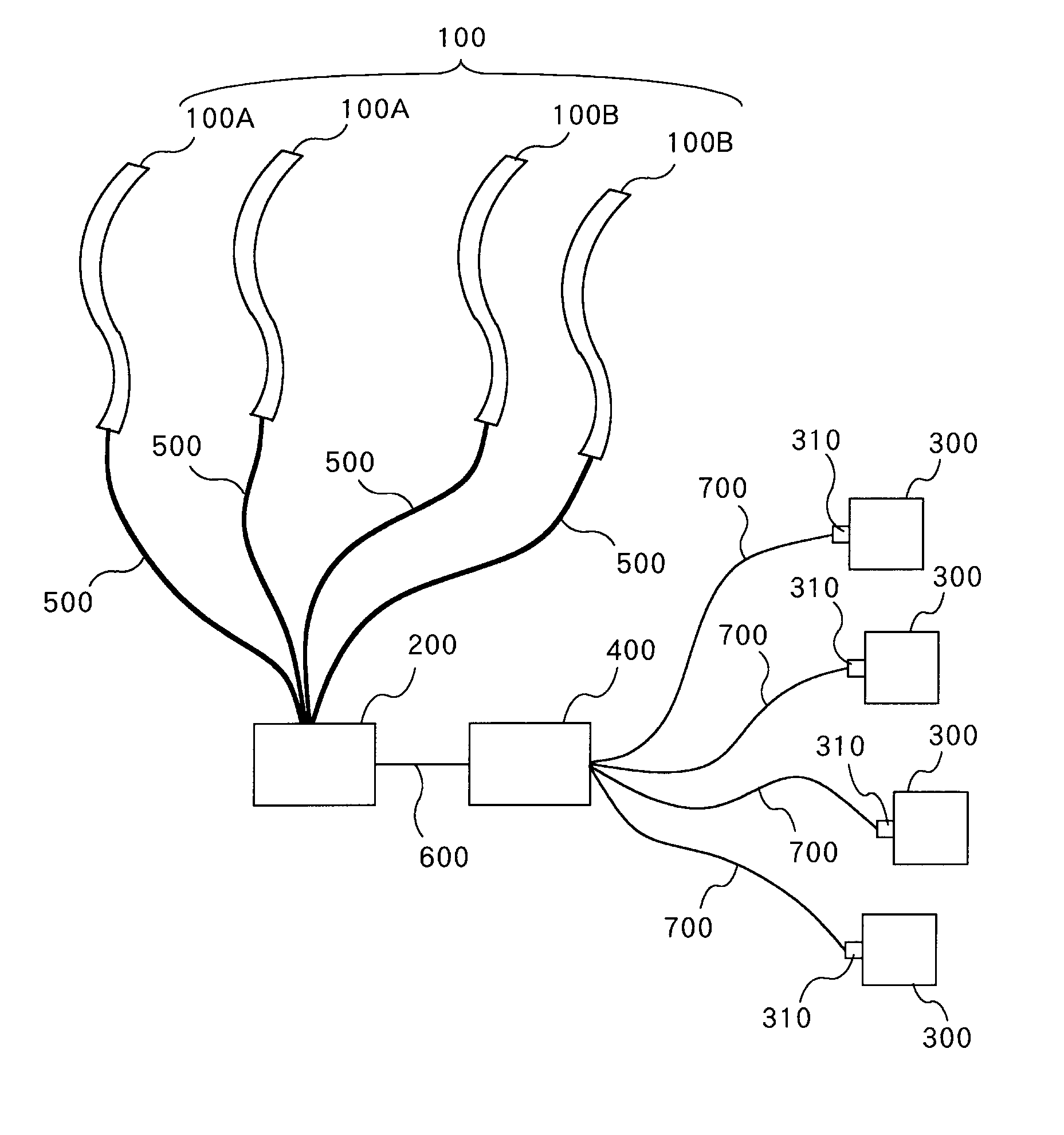
[0089]FIG. 1 is a view schematically showing the entire configuration of a training apparatus according to an embodiment of the present invention.

[0090]As shown in FIG. 1, the training apparatus according to this embodiment comprises a tight fitting band 100, a main device 200, a measuring segment 300, and a control segment 400. In this embodiment, although the main device 200 is described as a separate component from the control segment 400, they can be integrated to each other as a single component.

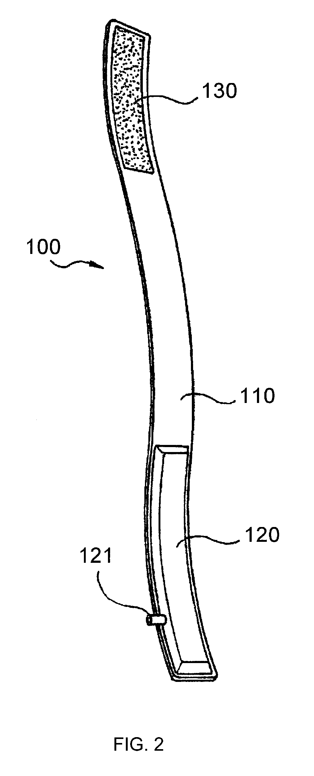
[0091]The tight fitting band 100 in this embodiment is configured as shown in FIGS. 2, 3, and 4. FIG. 2 is a perspective view showing an embodiment of the tight fitting band 100. FIGS. 3 and 4 are views illustrating how the tight fitting device 100 is used.

[0092]The tight fitting band 100 in this embodiment comprises a plurality of, more specifically, four members as shown in FIG. 1. The reason why there are four tight fitting bands 100 is to allow compression of the arms and legs of a ...

second embodiment

[0179]The training apparatus according to the second embodiment is basically identical to the one in the first embodiment. In particular, the training apparatus according to the second embodiment is identical to the one in the first embodiment in terms of the hardware configuration described with reference to FIGS. 1 to 6 in the first embodiment.

[0180]In addition, the training apparatus according to the second embodiment is also identical to the one in the first embodiment in terms of the functional block shown in FIG. 7. However, the functions of the main control unit 412 and the pulse wave analyzing unit 413 that are provided when the automatic mode is chosen in the second embodiment are slightly different from those provided when the automatic mode is chosen in the first embodiment. In addition, the second embodiment is different from the first embodiment in terms of the information entered by using the input device when the automatic mode is chosen, as well as the information wh...


PUM


Abstract

To provide a training apparatus for effective and safe performance of KAATSU training.A training apparatus is made up of a tight fitting band 100, a main device 200, a measuring segment 300, and a control segment 400. The tight fitting band 100 is wrapped around a predetermined region of a limb. The tight fitting band 100 has an air-tight inflatable bag. The compression force applied to the limb can be varied by supplying the air to and removing the air from the inflatable bag. The main device 200 controls the supply and removal of the air into and from the inflatable bag. The measuring segment 300 is attached to the limb around which the tight fitting band 100 is wrapped to measure the magnitude of a pulse wave. The control segment 400 determines, in preprocessing performed before the KAATSU training, the pulse wave component at a time point at which the magnitude of the pulse wave reaches the maximum, and chooses, as an appropriate gas pressure, the pressure within the inflatable bag that is produced at a time point at which such a pulse wave is generated that is obtained by means of multiplying the pulse wave component at a time point at which the magnitude of the pulse wave reaches the maximum with a numeral equal to or larger than 0.2 but smaller than 1.

Description

TECHNICAL FIELD[0001]The present invention relates to a technique for performing a training method that has been practiced and spread as KAATSU training in a safer or more effective manner.BACKGROUND ART[0002]Mr. Yoshiaki Sato, the present inventor, has conducted studies for quite some time in order to develop a muscle strength increasing method for easy, safe, and effective muscle development, and put together the accomplishments into a patent application having Japanese Patent Application No. 5-313949, which has been granted as Japanese Patent No. 2670421.[0003]The muscle strength increasing method according to the subject patent, which involves the application of pressure, is a distinctive non-conventional one. This muscle strength increasing method (hereinafter, referred to as “KAATSU training (registered trademark) method”) is based on the following theoretical concept.[0004]Muscles are composed of slow-twitch muscle fibers and fast-twitch muscle fibers. Slow-twitch muscle fibe...

Claims


Application Information

Patent Timeline
Patent Type & Authority Patents(United States)
IPC IPC(8): A61B5/02A63B21/008A63B71/00A63B21/002A61B17/135A63B21/00A63B71/06A63B21/055
CPCA63B21/0023A61B17/1355A63B21/0085A63B21/4025A63B71/0622A63B21/0552A63B2071/0627A63B2213/006A63B2220/56A63B2220/64A63B2220/805A63B2225/62A63B2230/04A63B2230/30A61B5/02116A61B5/022A63B24/0087A61H2201/165A63B2024/0078A61H2205/06A61H2205/10A63B69/0059A63B23/03508A63B2071/0655A63B2208/053A63B2209/10A63B21/4017A63B2225/74
Inventor SATO, YOSHIAKI
Owner KAATSU JAPAN
Learn More