
Implantable wireless electrocardiogram sensor device

a sensor device and wireless technology, applied in the field of implantable wireless electrocardiogram sensor devices, can solve the problems of inability to unlimitedly increase a potential difference, current reverse flow, and the lik

Active Publication Date: 2017-01-03
IND ACADEMIC COOPERATION FOUND KEIMYUNG UNIV
View PDF10 Cites 1 Cited by
  • Summary
  • Abstract
  • Description
  • Claims
  • Application Information

AI Technical Summary

Benefits of technology

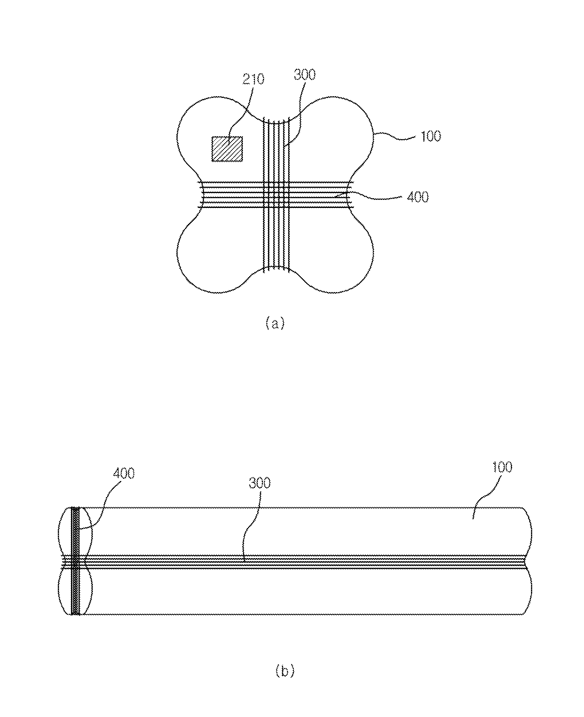
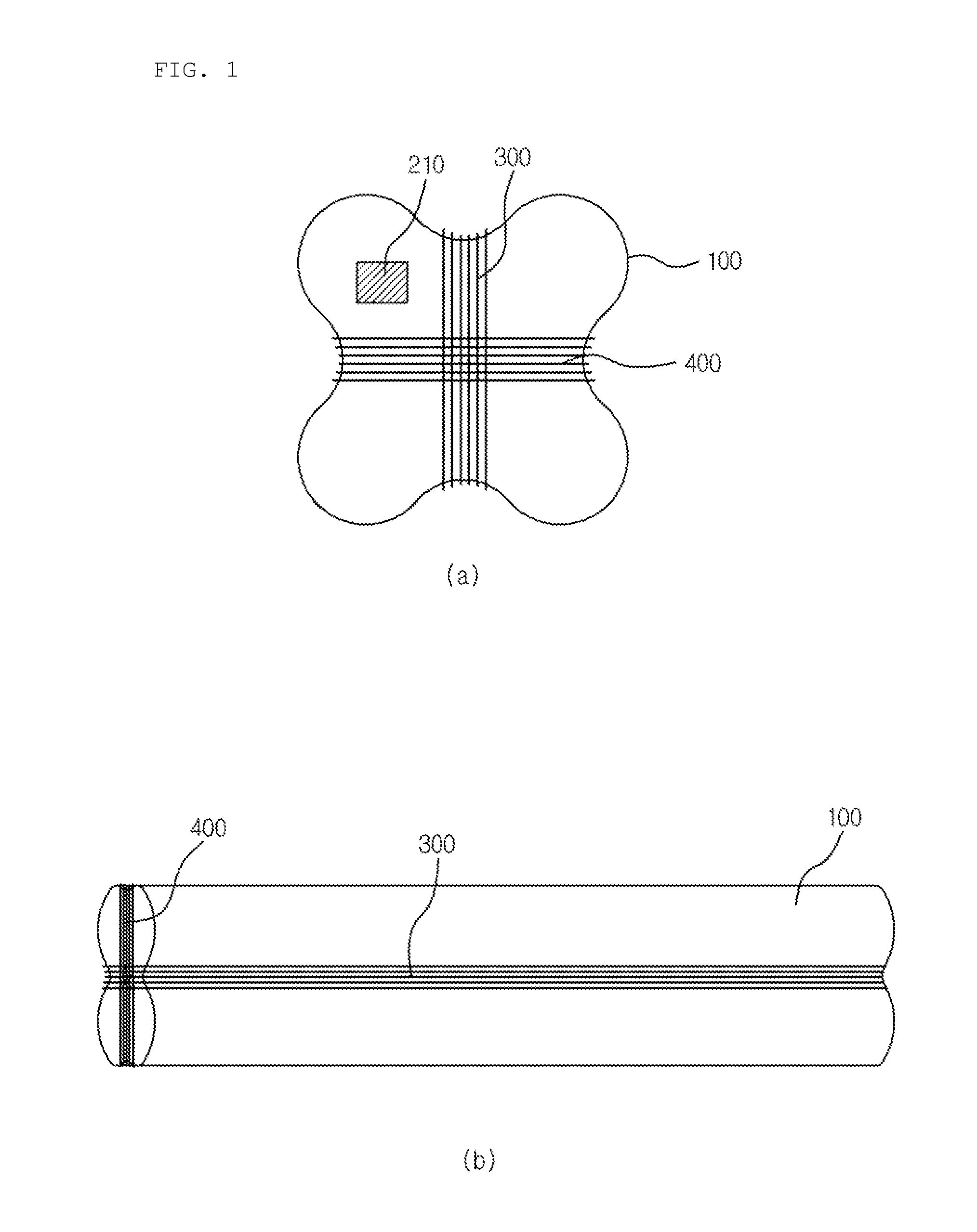
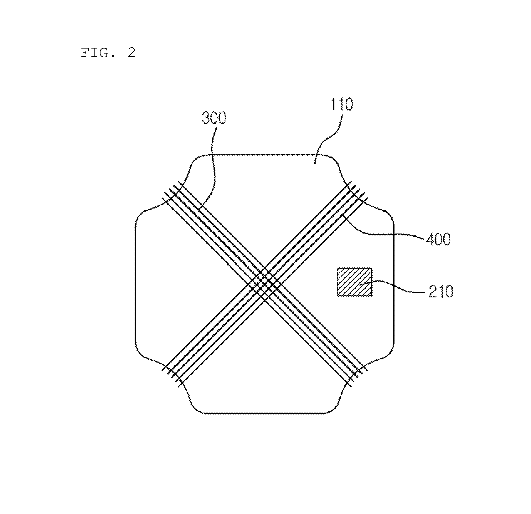
[0013]The implantable wireless electrocardiogram sensor device according to the present invention has the form implanted into a part of a heart or a human body for measuring electrocardiogram, includes the constituent elements for wireless charging in order to continuously transmit a signal for 24 hours, and is configured so that a length of the coil is sufficiently secured so as to perform wireless charging even at a remote distance and the antenna for transceiving is also installed to be wound around the capsule, and has the structure, in which the coil for wireless charging and the antenna for transceiving are wound around the electrocardiogram sensor device in the form of the small implantable capsule while crossing each other, so that it is possible to easily implant the implantable wireless electrocardiogram sensor device into a measurement region of the human body, measure and monitor electrocardiogram for a long time, and efficiently transceive wireless electrocardiogram data.

Problems solved by technology

However, when it is necessary to enlarge an electrocardiogram graph in order to obtain fine information, most of the electrocardiogram measuring equipment in the related art directly increases a potential difference to obtain a more precise result.
However, it is impossible to unlimitedly increase a potential difference, and when a potential difference is increased, a phenomenon, in which a current reversely flows, may occur due to a potential difference with a body.
However, when a predetermined lead is not attached onto a body for each equipment, there is a problem in that it is impossible to read a measured electrocardiogram signal or obtain necessary information.
Further, the existing electrocardiogram equipment adopts a fixed unit recording method according to a time order, so that it is very inconvenient to variously make a search according to a situation.
Accordingly, in order to search for stored material in electrocardiogram equipment capable of storing materials, it is necessary to inconveniently search for the material according to a recorded order.
In order to solve the problem, an implantable electrocardiogram sensor, which is directly transplanted or implanted into a human body to more accurately measure a signal, has been developed, but the implantable electrocardiogram sensor needs to continuously transmit a signal for 24 hours, so that there is a problem in that a capacity of a power supply needs to be large, and when a large capacity battery is used in order to solve the problem, the implantable electrocardiogram sensor has a large size, so that an extensive surgical operation needs to be performed in order to implant the implantable electrocardiogram sensor into the human body.

Method used


Image

  • Implantable wireless electrocardiogram sensor device
  • Implantable wireless electrocardiogram sensor device
  • Implantable wireless electrocardiogram sensor device

Examples


Embodiment Construction

[0019]Advantages and features of the present invention and methods for accomplishing the same will be described through the exemplary embodiments described in detail below together with the accompanying drawings. However, the present invention is not limited to the exemplary embodiments described herein, and may be implemented in other forms. However, the present exemplary embodiments are provided for describing the present invention in detail so that those skilled in the art may easily carry out the technical spirit of the present invention.

[0020]In the drawings, the exemplary embodiments of the present invention are not limited to the illustrated specific forms, but are exaggerated for the purpose of clarity. In addition, like reference numerals designate like elements throughout the specification.

[0021]In the present specification, the term “and / or” is understood to include at least one of the constituent elements that are enumerated in the context. In addition, a singular form a...


PUM


Abstract

Disclosed is an implantable wireless electrocardiogram sensor device, including: a cylindrical capsule provided with four recesses on a lateral surface thereof in a longitudinal direction thereof at equal intervals; electrodes installed on upper and lower surfaces of the cylindrical capsule and configured to measure electrocardiogram; a wireless electrocardiogram sensor module installed inside the capsule; a data transceiving antenna wound around two recesses symmetrical at a center; and a coil for charging wound around the remaining two recesses in a direction vertical to the antenna.

Description

CROSS REFERENCE TO PRIOR APPLICATIONS[0001]This application is a National Stage Application of PCT International Patent Application No. PCT / KR2014 / 000757 filed on Jan. 27, 2014, under 35 U.S.C. §371, which claims priority to Korean Patent Application No. 10-2013-0011250 filed on Jan. 31, 2013, which are all hereby incorporated by reference in their entirety.TECHNICAL FIELD[0002]The present invention relates to an implantable electrocardiogram sensor, and more particularly, to an implantable wireless electrocardiogram sensor device, which is easily implantable into a part of a body, and capable of continuously measuring and efficiently monitoring electrocardiogram.BACKGROUND ART[0003]An electrocardiogram records a change in a voltage by installing a sensor on a skin around a heart. The voltage measured by the sensor installed on the skin has an analog characteristic. A general method of measuring an electrocardiogram is a method of measuring a change in a voltage by using a potential...

Claims


Application Information

Patent Timeline
Patent Type & Authority Patents(United States)
IPC IPC(8): A61B5/042H02J5/00H02J7/02A61B5/0402A61B5/00
CPCA61B5/0422A61B5/0006A61B5/0031A61B5/0402A61B5/042A61B5/686A61B5/6861H02J5/005H02J7/025A61B2560/0219H02J50/12H02J7/00034A61B5/283A61B5/287A61B5/318H02J2310/23H04B7/24
Inventor KIM, YOON NYUNLEE, JONG HAPARK, HEE JUNPARK, HYOUNG SEOBSON, CHANG SIK
Owner IND ACADEMIC COOPERATION FOUND KEIMYUNG UNIV
Learn More