
Ozonated liquid dispensing unit

a technology of ozonated liquid and dispensing unit, which is applied in the direction of liquid degasification, detergent compounding agent, separation process, etc., can solve the problems of poor cleaning and sanitizing, system difficulty maintenance, and increased equipment and supply costs, so as to achieve effective and longer lasting cleaning and sanitizing solution

Active Publication Date: 2016-12-20
CLEANCORE SOLUTIONS LLC
View PDF147 Cites 36 Cited by
  • Summary
  • Abstract
  • Description
  • Claims
  • Application Information

AI Technical Summary

Benefits of technology

This patent describes a device that produces and dispenses an ozonated liquid for cleaning and sanitizing various items. The device includes a reaction vessel that breaks up bubbles of ozone gas in the liquid, resulting in a more effective and longer-lasting cleaning and sanitizing solution. The device is compact, easy to install, and uses multiple dielectric cells to create a high concentration of ozone gas mixed with water to form the ozonated liquid. The technical effects of this device include improved cleaning and sanitizing efficiency, as well as a more convenient and compact installation.

Problems solved by technology

Prior attempts to provide an ozonated liquid in a kitchen environment have failed to provide an ozonated liquid with sufficient concentrations of ozone resulting in poor cleaning and sanitizing.
Without sufficient ozone concentration, conventional cleaning and sanitizing methods may still be necessary at extra labor, equipment, and supply costs.
Such systems are difficult to maintain.
Such systems are often too large and too bulky to be effectively used in some residential or commercial applications.
Many of these systems are also too expensive for use in the home or are not economical to be used in commercial applications.
Such systems often require significant mechanical alterations to existing water supply and delivery systems.
Further, many previous systems cannot be used with multiple, different dispensing applications.

Method used


Image

  • Ozonated liquid dispensing unit
  • Ozonated liquid dispensing unit
  • Ozonated liquid dispensing unit

Examples


Embodiment Construction

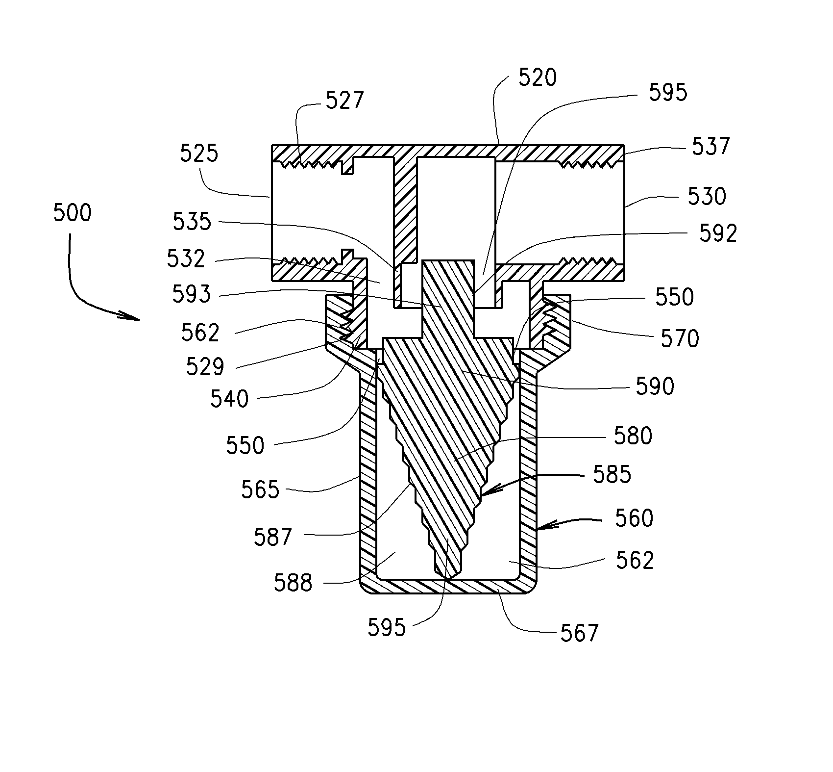
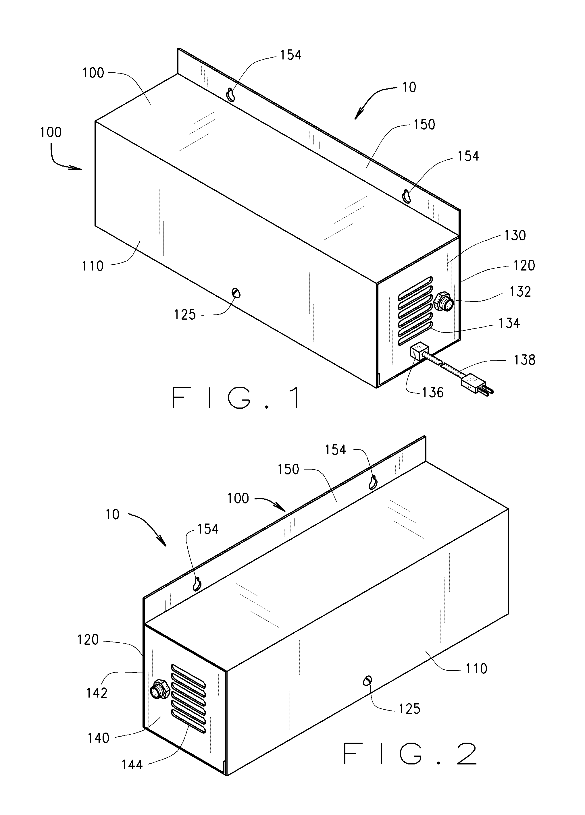
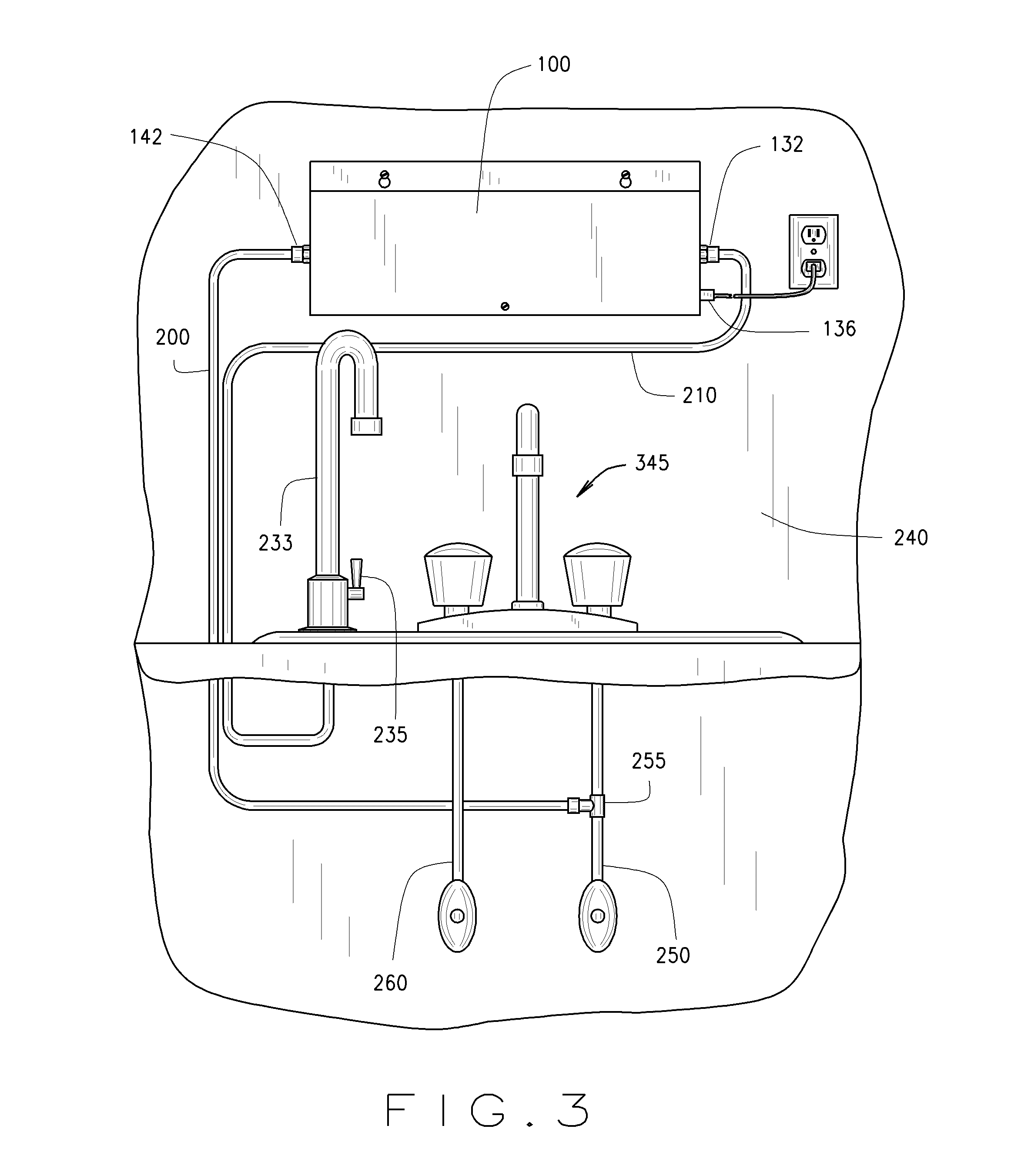
[0040]An ozonated liquid dispensing unit is described herein. With reference to FIGS. 1 and 2, an ozonated liquid dispensing unit 10 is shown. The unit 10 includes a housing 100, a removable housing cover 110 and a housing support 120. The housing 100, the housing cover 110, and the housing support 120 form a rectangular, box-like structure that houses the internal components of the unit 10. The housing 100 may be designed or engineered in other shapes and configurations. The housing 100, the housing cover 110, and the housing support 120 are made from sturdy or rugged materials, such as stainless steel, aluminum, or metals. Plastics and other composite materials may also be utilized in the construction of the housing 100, the housing cover 110 and the housing support 120.

[0041]As shown in FIGS. 4-6, the housing cover 110 is removed from the housing 100 to show the housing support 120, which receives and stabilizes the internal components of the unit 10. The housing cover 110 may be...


PUM

PropertyMeasurementUnit
diameteraaaaaaaaaa
diameteraaaaaaaaaa
surface tensionaaaaaaaaaa

Abstract

A reaction vessel and an ozonated liquid dispensing unit are described herein. The unit produces and dispenses an ozonated liquid that may be used to clean and sanitize a variety of articles or used in conjunction with cleaning processes and other apparatus. The reaction vessel is incorporated into the unit to reduce bubbles of ozone gas and to break up bubbles of ozone gas in the ozonated liquid to provide a more effective and longer lasting cleaning and sanitizing solution.

Description

CROSS REFERENCE TO RELATED APPLICATION[0001]This application is a continuation-in-part of U.S. Nonprovisional patent application Ser. No. 12 / 816,837 filed Jun. 16, 2010, which is a continuation-in-part of U.S. Nonprovisional patent application Ser. No. 12 / 179,335 filed Jul. 24, 2008, which are both hereby incorporated by reference.FIELD OF INVENTION[0002]The present invention relates to an ozonated liquid dispensing unit that produces and dispenses an ozonated liquid that may be used to clean and sanitize a variety of articles or used in conjunction with cleaning processes and other apparatus, and the present invention further relates to a reaction vessel that may be used with the ozonated liquid dispensing unit.BACKGROUND OF INVENTION[0003]Prior attempts to provide an ozonated liquid in a kitchen environment have failed to provide an ozonated liquid with sufficient concentrations of ozone resulting in poor cleaning and sanitizing. Without sufficient ozone concentration, conventiona...

Claims


Application Information

Patent Timeline
Patent Type & Authority Patents(United States)
IPC IPC(8): B01D19/02C11D3/20A23B7/157A23B7/158C01B13/11C11D3/39C11D3/50C11D3/386A61L2/18
CPCB01D19/02A23B7/157A23B7/158A23L5/57A61L2/183C01B13/11C11D3/2093C11D3/38636C11D3/39C11D3/50A23V2002/00A61L2/18C01B2201/32C01B2201/40C01B2201/62C01B2201/64A23V2200/10A23V2250/128A61L2202/11C11D3/04
Inventor LYNN, DANIEL W.
Owner CLEANCORE SOLUTIONS LLC
Learn More