
Acoustic radiating membrane arrangement for a striking watch

a technology of acoustic radiating membrane and a watch, which is applied in the direction of mechanical time indication, sound producing devices, instruments, etc., can solve the problems of low acoustic efficiency, limited adaptation possibilities, and inability to efficiently radiate in this frequency range of conventional external parts, so as to achieve good acoustic efficiency and low internal damping

Active Publication Date: 2016-12-13
MONTRES BREGUET
View PDF21 Cites 1 Cited by
  • Summary
  • Abstract
  • Description
  • Claims
  • Application Information

AI Technical Summary

Benefits of technology

[0008]It is therefore an object of the invention to overcome the aforementioned prior art drawbacks by providing an acoustic radiating membrane arrangement for a musical watch or a striking watch, created to improve acoustic efficiency over a broad frequency range and also to ensure the impermeable sealing and resistance to high external pressure of the watch case.
[0014]One advantage of the acoustic radiating membrane arrangement lies in the fact that the geometry and connection of several, notably superposed membranes are each specifically optimised to guarantee mechanical strength and impermeable sealing, and also to improve and make uniform acoustic radiation, mainly in a frequency band from 1 kHz to 4 kHz.
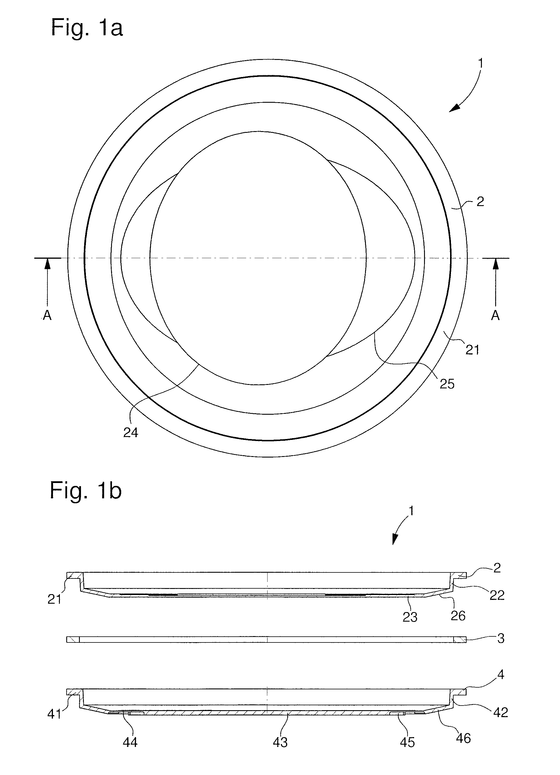
[0015]Advantageously, at least a first membrane is configured to radiate efficiently the frequencies in a first frequency band, which may be the frequency band from 2 kHz to 4 kHz. This first membrane, secured inside the watch case, ensures good sealing of the portion of the watch case that includes the mechanical movement of the striking or musical watch. This acoustic membrane is made of a determined material and with a defined general width having plan dimensions comparable to the plan dimensions of a watch case or crystal.
[0016]Advantageously, at least a second membrane is configured with a central portion in the form of a piston, similar to the principle of a loudspeaker. Openings may also be made in the central portion. This makes it possible to ensure an increase in vibration amplitude, especially in a second frequency band, which may be a frequency band from 1 kHz to 2 kHz. As with the first membrane, this second acoustic membrane is made of a determined material and with a defined general width having dimensions that may be comparable to those of the first membrane. The acoustic response of the second membrane is relatively uniform in this frequency range.
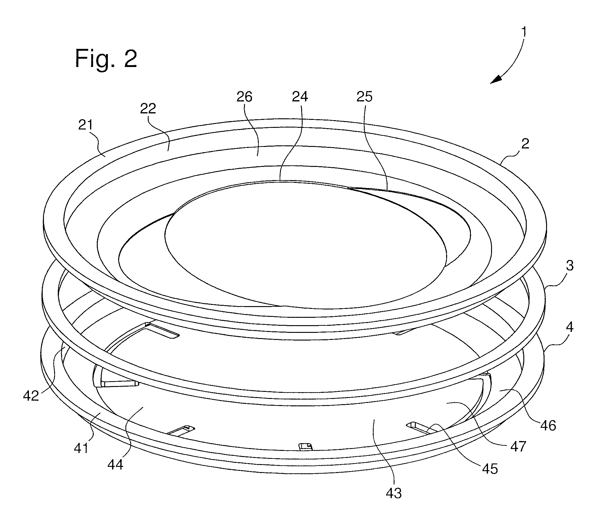
[0017]Advantageously, the second membrane is superposed on the first membrane, for example by means of a spacer ring. Owing to the assembly of the two membranes with the spacer ring, there remains a cavity between the two membranes, which is tuned, to within 100 Hz, to one of the two fundamental vibration frequencies of the two membranes. Further, the openings, which are made in the central portion of the second membrane, may be dimensioned such that the assembly of the two membranes provides an acoustic cavity of the Helmholtz resonator type. This allows the acoustic level of the striking or musical watch to be increased at certain frequencies.
[0022]With such membranes, extension of the sound range can be combined with very low internal damping, which makes it possible to obtain very good acoustic efficiency.

Problems solved by technology

Generally, in such a musical or striking watch, acoustic efficiency, based on the complex vibroacoustic transduction of the external parts, is low.
The configurations of these external parts are also dependent upon the aesthetic appearance of the watch and operating stresses, which may limit adaptation possibilities.
Conventional external parts do not allow efficient radiation in this frequency range.
In these conditions, a pierced membrane cannot therefore be used between the back cover and the mechanical movement.
Further, a membrane having a too low level of stiffness cannot ensure sufficient resistance to external pressure without risking damage to the movement, which constitutes drawbacks.
However, the two other bell-shaped membranes are not arranged to improve the acoustic level of the sound produced by the striking device, which is a drawback.

Method used


Image

  • Acoustic radiating membrane arrangement for a striking watch
  • Acoustic radiating membrane arrangement for a striking watch
  • Acoustic radiating membrane arrangement for a striking watch

Examples


Embodiment Construction

[0029]In the following description, reference will mainly be made to the configuration of the acoustic radiating membrane arrangement intended to equip a musical watch, or a striking watch. The acoustic radiating membranes may be made in a complex shape to increase the vibration amplitude of the various notes produced in a watch case. Preferably, the membranes are dimensioned and configured to amplify, in particular, the first vibration mode, or even a second vibration mode, in a frequency band from 1 kHz to 4 kHz.

[0030]FIGS. 1a, 1b and 2 show an embodiment of the acoustic radiating membrane arrangement 1, which may equip a musical watch or a striking watch. Depending on the shape of the watch case, the acoustic radiating membrane arrangement 1 may, seen from above, have a generally rectangular, or polygonal, or preferably circular shape, as shown in FIG. 1a.

[0031]The acoustic radiating membrane arrangement 1 includes at least a first acoustic membrane 2 superposed on a second acou...


PUM


Abstract

There is provided an acoustic radiating membrane arrangement for a striking or musical watch. The arrangement includes a first membrane arranged superposed on a second membrane. Peripheral edge portions of the two membranes are intended to hold the membranes inside a watch case. The first acoustic radiating membrane is configured to radiate efficiently the frequencies in a first frequency band. The second acoustic radiating membrane is configured to radiate efficiently the frequencies in a second frequency band that is different from the first frequency band. A spacer ring is also disposed between the peripheral edge portions of the first membrane and of the second membrane to define an acoustic cavity.

Description

[0001]This application claims priority from European patent application 14189091.3 filed Oct. 15, 2014, the entire disclosures of which is hereby incorporated herein by reference.FIELD OF THE INVENTION[0002]The invention concerns an acoustic radiating membrane arrangement for a musical watch, or a striking watch. This arrangement includes at least two membranes superposed inside the watch case for the acoustic radiation of a sound generated in the watch.BACKGROUND OF THE INVENTION[0003]In a watch, a striking mechanism may be provided to generate a sound or piece of music. To achieve this, the gong of the striking watch or the vibration plate of the musical watch are generally arranged inside the watch case. Thus, the vibrations of the gong or the vibration plate strips are transmitted to the various external parts of the watch. These external parts are, for example, the case middle, the bezel, the crystal and the back cover of the watch case. These large external parts start to radi...

Claims


Application Information

Patent Timeline
Patent Type & Authority Patents(United States)
IPC IPC(8): G04B37/00G04B21/00
CPCG04B21/00G04B37/0075G04B21/08G10K13/00G04B37/11G10K1/10
Inventor KARAPATIS, POLYCHRONIS NAKISSARCHI, DAVIDEKADMIRI, YOUNES
Owner MONTRES BREGUET
Learn More