Flash steam generator

a generator and flash technology, applied in the field of flash steam generators, to achieve the effect of increasing the surface area contact, high surface area ratio, and efficient conversion into steam or superheated water

Active Publication Date: 2016-12-13
WILLIAMS JENNIFER BETH +1
View PDF10 Cites 6 Cited by
  • Summary
  • Abstract
  • Description
  • Claims
  • Application Information

AI Technical Summary

Benefits of technology

[0010]The illustrated embodiments of the invention are directed to a flash steam generator designed to function within a portable steam or steam / vacuum cleaner. The illustrated embodiment addresses the described deficiencies in the current field of small portable steam cleaning units by providing 1 a powerful source of steam with 2 rapid startup time of less than ten seconds and 3 is compact enough to be housed within hand-held devices. The illustrated embodiment achieves these objectives by 1 using a heater coil to directly heat the water or cleaning solution instead of heating a metal block that then heats the water or cleaning solution (or more generally referenced as “fluid”), and 2 increasing the surface area contact between the water or cleaning solution and the heating element heater coil. The illustrated embodiment utilizes the heater coil itself to form at least part of the surface of a defined flow path such that at least 50% of the surface area of the water or cleaning solution flowing through this path is in contact with the outer surface of the heater coil which may include, but is not limited to, an outer surface covering or housing, an insulating coating, or both. A defined flow path is a channel created by the space between loops of the heater coil, wherein the majority of the liquid flow volume follows the path of the channel. More than one heater coil may be used to create this defined flow path. Additional surfaces, walls, or barriers are used to complete the defined flow path by surrounding or sandwiching the heater coils between them. The defined flow path follows a route that increases its length within a given volume as defined by the housing and may be a spiral or helical path, a zig-zag, or some other convoluted path. In a preferred embodiment, the flash steam generator comprises an inner casing, an outer casing, and a heater coil. The heater coil is wrapped around the outside surface of the inner casing in a helical pattern with open space left between successive loops of the heater coil. An outer casing encloses the inner casing and heater coil such that the heater coil is not exposed to the surrounding environment, except through openings that allow the inflow and outflow of liquids and gases. This configuration effectively creates a channel between the inner and outer casings that follows the path created by the gap between the successive loops of the heater coil. Water or cleaning solution is efficiently converted into steam or superheated water as it is pumped through the channel between heater coil loops and receives heat transferred from the heater coil. Efficient steam generation is promoted by two means. First, because the water or cleaning solution travels through the channel between two adjacent heater coil loops, it is being heated from both sides of the channel. This results in a high ratio of surface area in contact with the heater coil relative to the volume of water or cleaning solution, which promotes heat transfer. Second, the helical path of the water or cleaning solution channel increases the length the water or cleaning solution has to travel while in contact with the heater coil, which further promotes heat transfer.

Problems solved by technology

First, because the water or cleaning solution travels through the channel between two adjacent heater coil loops, it is being heated from both sides of the channel.

Method used


Image

  • Flash steam generator
  • Flash steam generator
  • Flash steam generator

Examples


Embodiment Construction

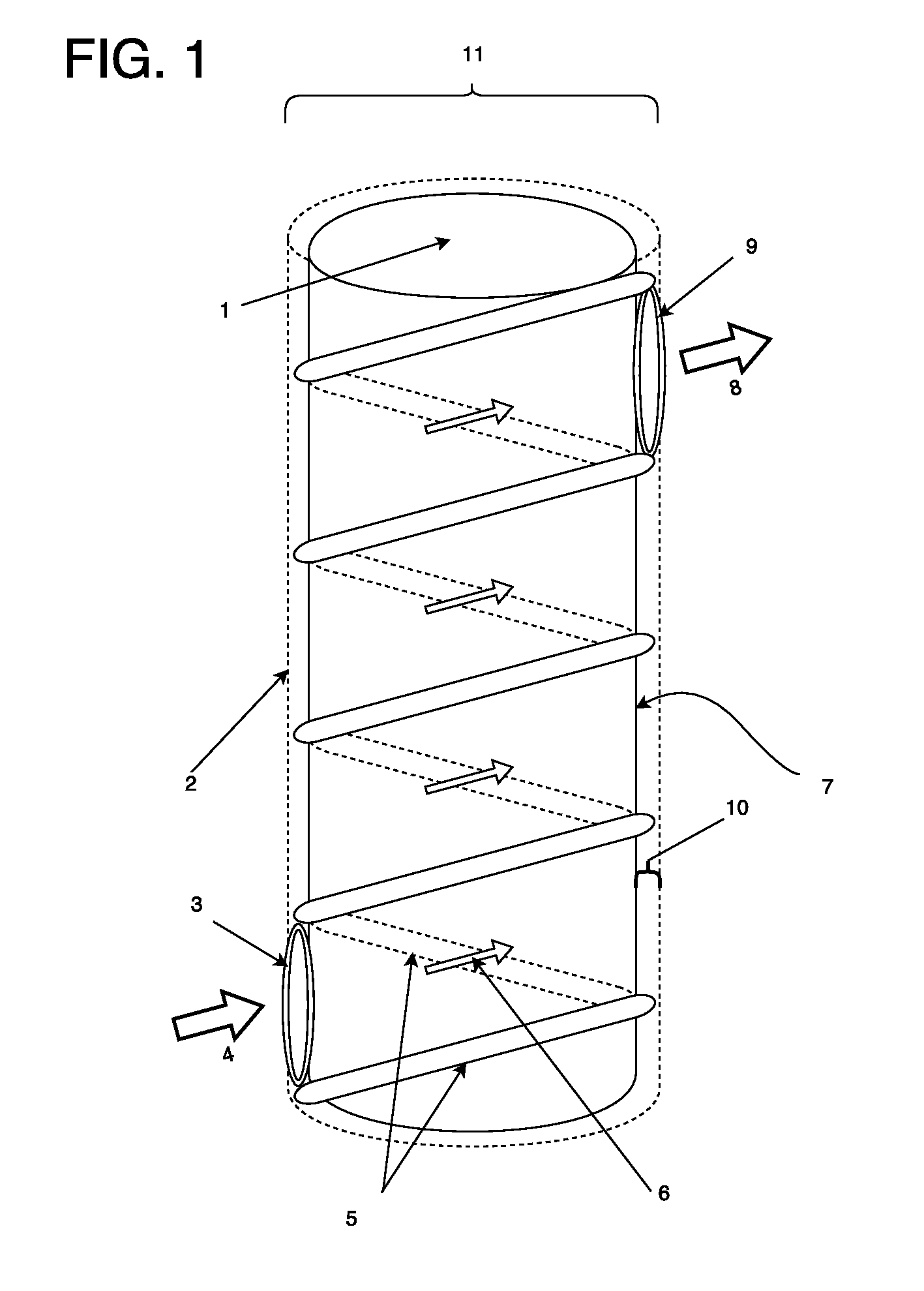
[0042]FIG. 1 illustrates a preferred embodiment of the steam generator 11 that comprises an inner casing 7 and an outer casing 2 with a heater coil 5 interposed in the space between the inner and outer casings 10, wherein the casings are cylindrical in shape. The heater coil 5 is wrapped around the inner casing 7 in successive loops, resulting in a helical pattern that extends up the length of the inner casing 7. The distance separating the surfaces of the inner and outer casings 7, 2 is such that the heater coil 5 loops are disposed within the space between the casings. The space created between the heater coil 5 loops and the surfaces of the inner and outer casings 7, 2 forms a continuous channel 6 that follows the helical route of the heater coil 5 loops. An inlet 3 provides an opening for the inflow of water or cleaning solution 4 pumped into the channel 6 created by the successive loops of the heater coil 5. The water or cleaning solution pumped up the channel 6 in-between the ...


PUM


Abstract

A steam generator for use within a portable steam generating system. The steam generator is composed of a heater coil looped around an inner casing in a helical pattern with a continuous gap left between successive loops. An outer casing encloses the inner casing and heater coil, creating a channel for fluid flow in the gap between successive loops of the heater coil and the inner and outer casings. An opening allows fluid to be pumped in one end of the channel and heated as it travels along the channel. The fluid is superheated by the heater coil loops and is converted into steam and expands upon depressurization after exiting the steam nozzle. This steam generator can be disposed within a handheld housing within a steam generating system.

Description

CROSS-REFERENCE TO RELATED APPLICATIONS[0001]This application claims priority to, and the benefit of the earlier filing date of: US patent application entitled Optimally compact ergonomic hand-held combination flash heated steam cleaning generator / wet & dry vacuum cleaner and container design, filed on Mar. 18, 2013, Ser. No. 13 / 736,040, pursuant to 35 USC 120, the contents of which are incorporated herein by reference in its entirety.BACKGROUND[0002]Field of the Invention[0003]CPC fields: L2501 / 14, B37 / 60, B27 / 00[0004]The disclosure relates to the field of flash steam generators for use within portable steam cleaning devices for both domestic and commercial use.[0005]Description of the Prior Art[0006]Portable steam cleaning devices are used for cleaning a variety of surfaces including floors, countertops, stovetops, tiles, glass, ceramic, clothing and upholstery. The application of high temperature steam can provide the requisite energy and solvent to solubilize greases, stains, di...

Claims


Application Information

Patent Timeline
Patent Type & Authority Patents(United States)
IPC IPC(8): B08B3/02A47L11/40A47L7/00
CPCA47L11/4086A47L7/0004A47L11/4016A47L11/4088B08B3/02B08B3/00B08B5/04B08B2230/01F22B1/28B05B14/10
Inventor WILLIAMS, JENNIFER BETHDUDA, CRAIG RAYNOLD
Owner WILLIAMS JENNIFER BETH
Why Eureka
Try Eureka