
Component reachable expandable heat plate

Inactive Publication Date: 2015-05-14
MONSON ROBERT J +2
View PDF10 Cites 2 Cited by
  • Summary
  • Abstract
  • Description
  • Claims
  • Application Information

AI Technical Summary

Benefits of technology

The invention provides a heat plate system with a flexible surface that can make good contact with heat-generating components of varying heights. The heat plate can expand during use, making it easier to control the temperature. The heat plate can also interface directly with the module's side walls and cooling mechanism, which makes thermal management more effective.

Problems solved by technology

The inventors have appreciated that employing heat plates to cool the numerous types of devices and components used in modern applications can present challenges.
This is difficult to accomplish using conventional fabrication techniques.
However, thermal interfaces are notoriously poor at conducting heat away from a chip, because they are typically made from materials which are highly conformable but not very thermally conductive.
For example, many thermal interfaces cause about a 50% loss in thermal conductivity when compared with direct contact between a chip and a heat plate.
However, the use of pastes can make module assembly problematic, because applying a paste on a set of chips having varying heights so that the paste atop each chip reaches the same height can be difficult.
In addition, pastes are messy, and can therefore make module maintenance difficult.

Method used


Image

  • Component reachable expandable heat plate
  • Component reachable expandable heat plate
  • Component reachable expandable heat plate

Examples


Embodiment Construction

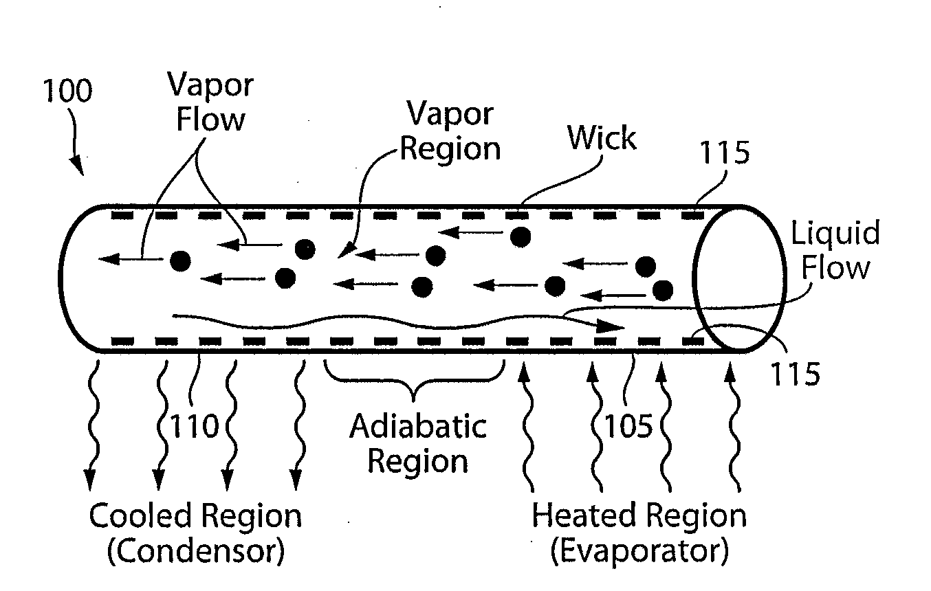
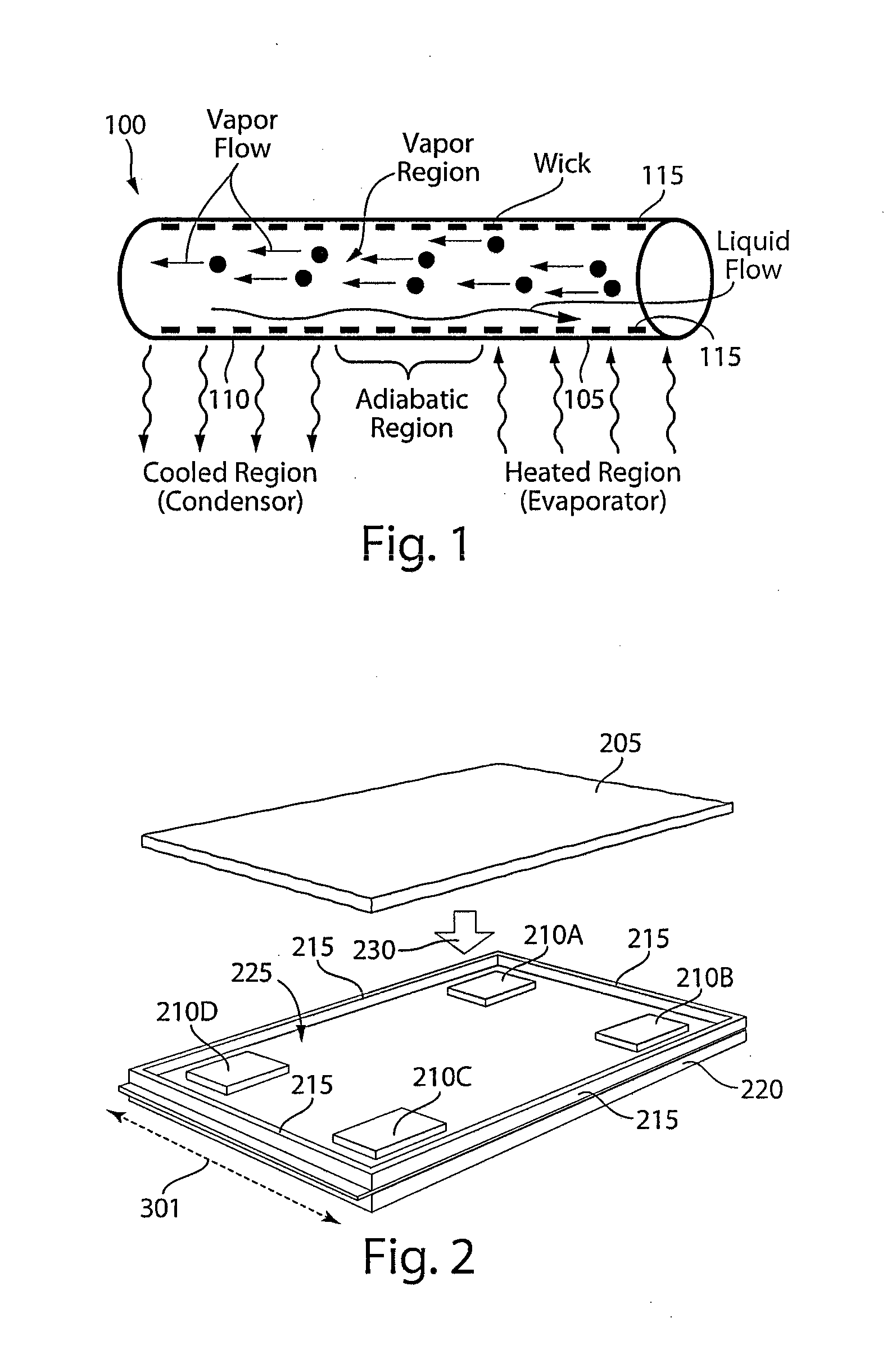
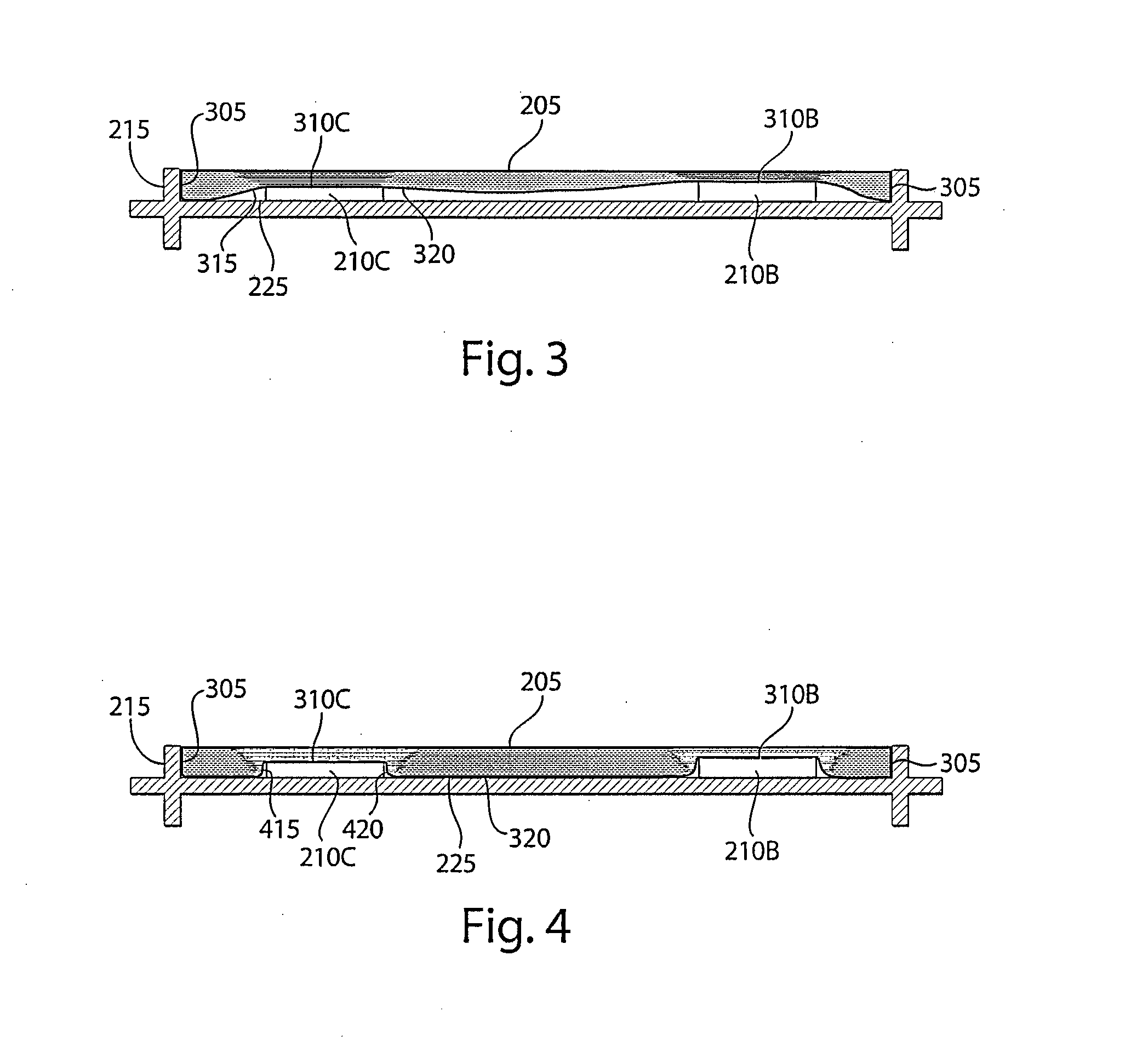
[0017]Some embodiments of the invention provide a heat plate system which includes a closed vessel having at least one surface that is pliable and / or flexible, allowing the vessel to come into close contact with contoured surfaces of heat-generating components of varying heights, and enabling effective heat transfer away from those components. In some embodiments of the invention, a heat plate may be expandable, such as upon the absorption of heat, so as to increase the component surface area with which the heat plate system comes into contact, and thereby improving thermal conductivity. In addition, some embodiments of the invention may provide a heat plate system for use with heat-generating components residing in a module housing which is designed to conduct heat to the housing's peripheral walls and / or a cooling mechanism, rather than to the housing's cover, to provide greater control and effectiveness with respect to heat transfer than conventional systems provide.

[0018]FIG. 2 ...


PUM


Abstract

Some embodiments of the invention provide a heat plate system that includes a closed vessel having at least one flexible surface. The flexible surface allows the vessel to come into intimate contact with heat-generating components (e.g., integrated circuits) residing at varying heights above the floor of a module (e.g., an avionics module). In some embodiments, the material may allow the heat plate to expand in response to absorbing heat, so that it may mold itself around the contours of different heat-generating components, increasing the surface area contact between the heat plate and the components, and increasing the heat plate's ability to conduct heat away from the components.

Description

FIELD OF INVENTION[0001]This invention deals generally with heat transfer, and more particularly with heat plates and / or heat pipes used in transferring heat away from one or more heat-generating components.BACKGROUND[0002]Proper thermal management is critical to the successful operation of many types of devices. In this respect, modern jet aircraft include numerous types of devices which generate significant heat during operation, including avionic electronics, radar and directed-energy systems. As an example, avionics components commonly use integrated circuits (hereinafter called “chips” for convenience) for computing applications which can generate significant heat during operation.[0003]Various techniques are known for transferring heat away from devices and / or their components during operation, to keep the devices functioning properly. For example, heat plates are commonly used to transfer heat away from the tops of the chip(s) in an avionics module toward the module's edge (e...

Claims


Application Information

Patent Timeline
IPC IPC(8): F28D15/02
CPCF28D15/02F28F2265/26H01L23/427H01L2924/0002H01L2924/00
Inventor MONSON, ROBERT J.KATTERHEINRICH, KENTLEE, YUNG-CHENG
Owner MONSON ROBERT J
Learn More