
Burner system and a method for increasing the efficiency of a heat exchanger

a heat exchanger and burner technology, applied in the field of burner systems and heat exchangers, can solve problems such as explosion or detonation, and achieve the effects of high gas friction, free forward flow, and fast combustion

Active Publication Date: 2016-12-06
TRIPLE E POWER LTD
View PDF46 Cites 21 Cited by
  • Summary
  • Abstract
  • Description
  • Claims
  • Application Information

AI Technical Summary

Benefits of technology

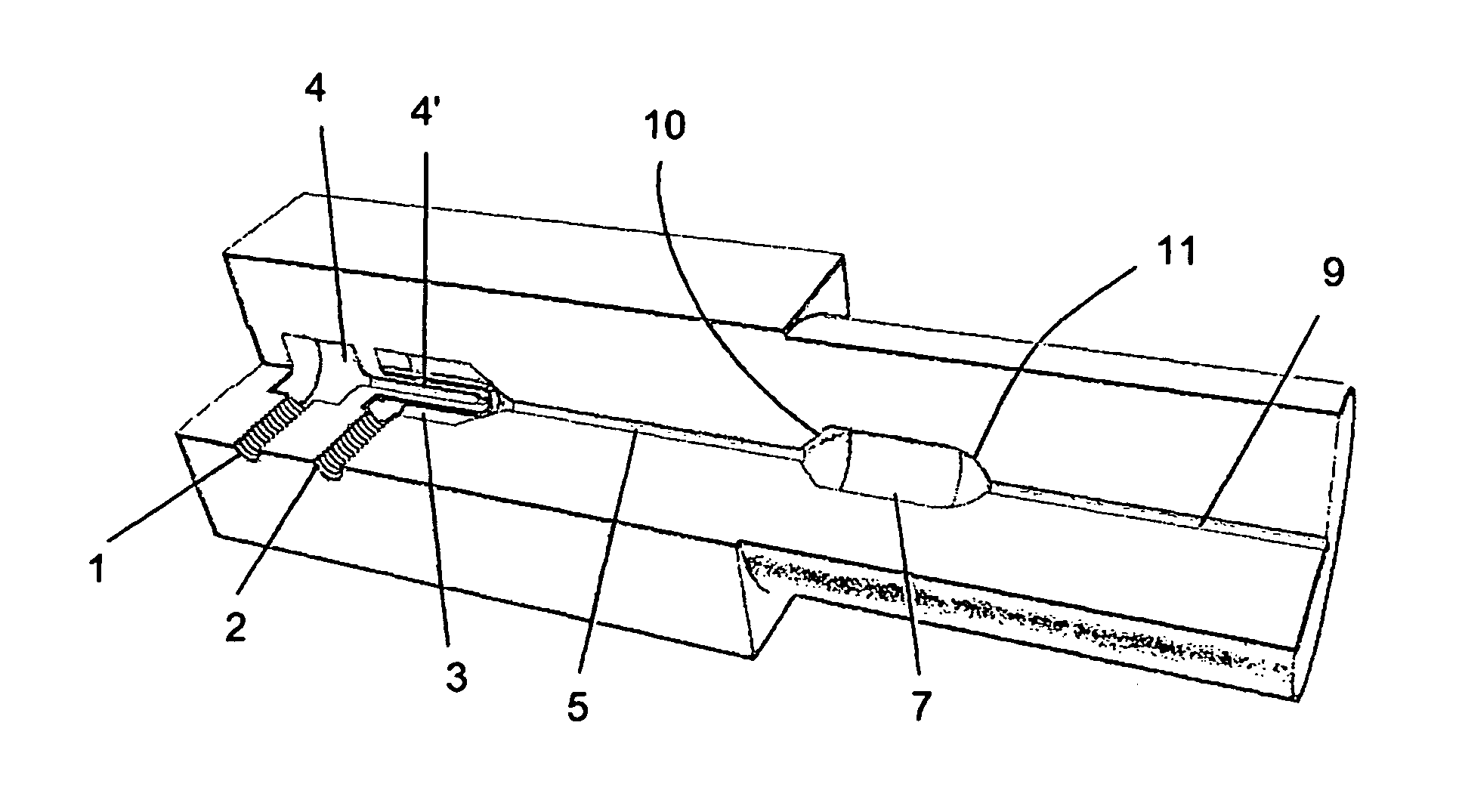
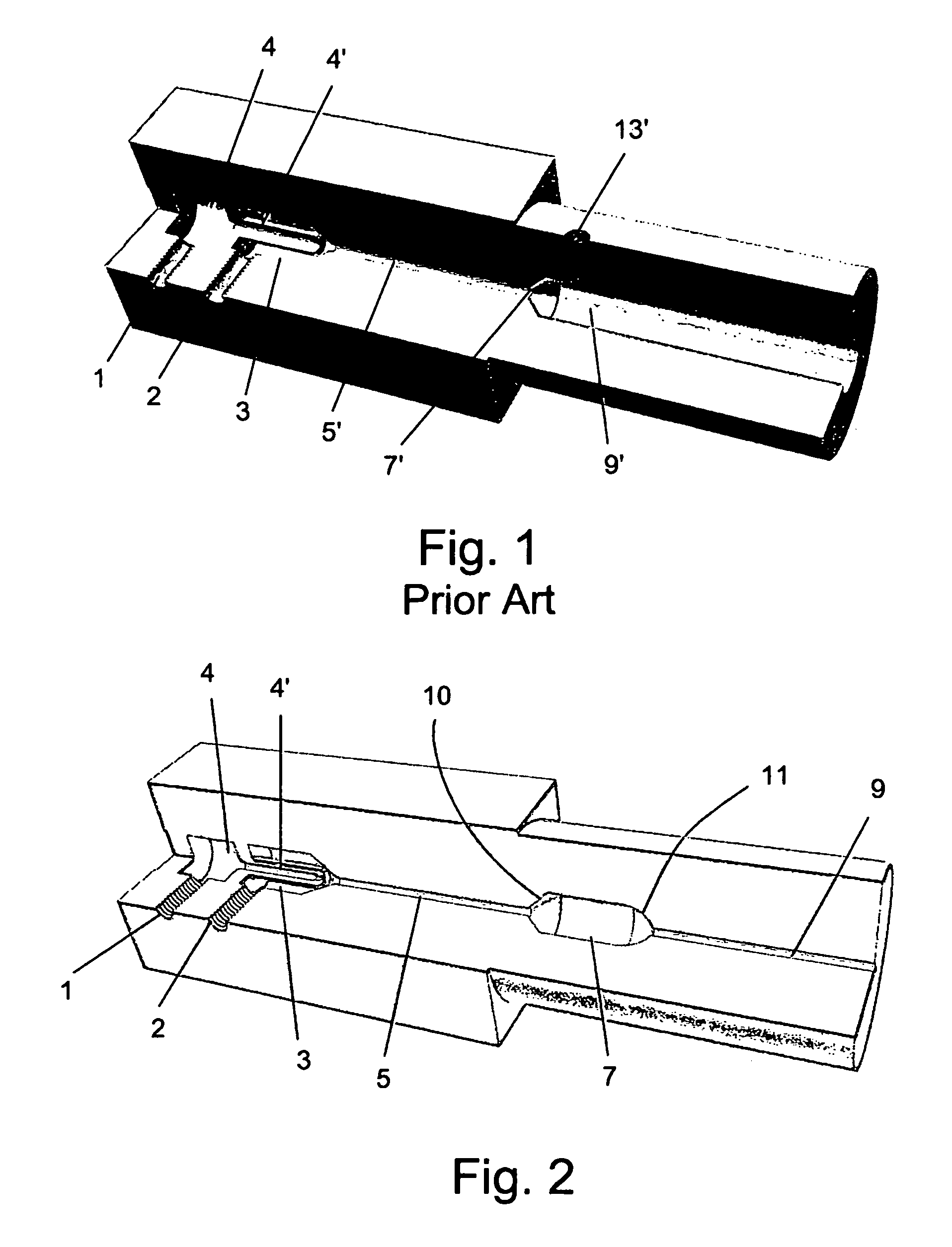
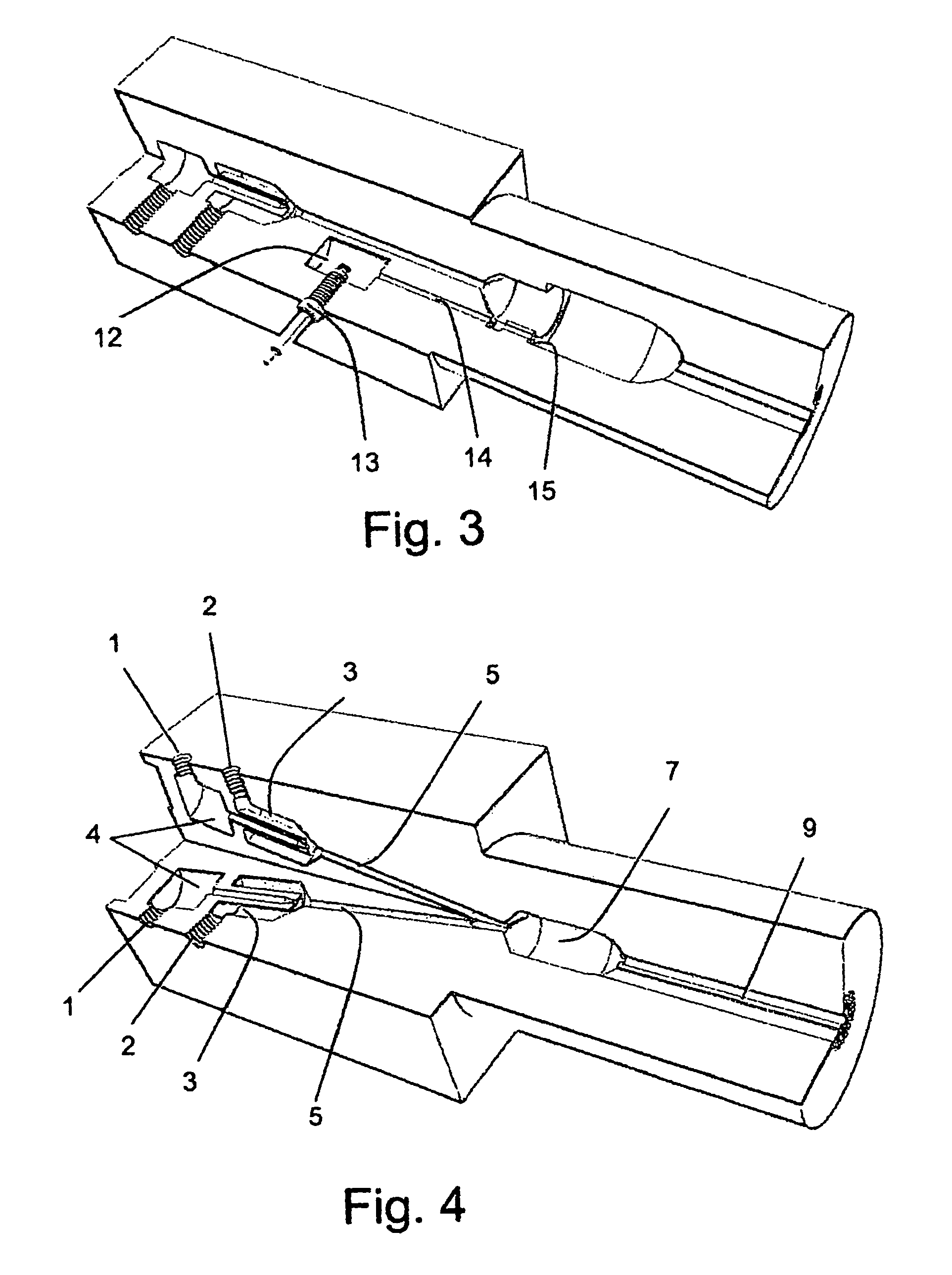
[0033]The pressure of the compressed compounds and the internal cross-sectional area and the surface characteristics of the inner surface of the friction channel are adapted to allow fast, free forward flow under pressure of the compounds through the friction channel into the reaction chamber and to create high gas friction for the much faster wave front of an explosion or detonation that takes place in the reaction chamber to prevent the wave front from passing backwards through the friction channel into the inlet chambers. In this way the friction channel is sufficiently blocked against the wave front of the explosion or detonation. This causes the continuous repeated interruption of the flow of the compressed compounds forward into the reaction chamber and allows the build-up of continuous repeating pulses of the compounds under pressure in the reaction chamber. This allows continuous repeating pulsing explosions or detonations to take place in the reaction chamber.
[0038]The burner systems of the invention can be adapted to function as a linear engine by fitting a partially cone shaped expansion chamber at the outlet end of the last reaction chamber. The expansion chamber is provided with inlets adapted to feed a fluid through channels into it and the system adapted such that the energy of explosions or detonations that take place in the reaction chamber or reaction chambers is used to heat the walls of the evaporation chamber thereby to rapidly evaporate the fluid.
[0040]In another aspect the invention is a method of increasing the efficiency of a heat exchanger comprising walls defining a reaction chamber for a combustion reaction. The method comprises the steps of initiating and maintaining controlled continuous pulsing explosions or detonations of at least two pressurized fluid compounds at very high temperatures.

Problems solved by technology

This creates specific fields of overlapping infrared radiation having sufficiently high temperature to ignite the compounds at a specific point inside the reaction chamber and thus initiates an explosion or detonation after a specific amount of compounds have entered the reaction chamber.

Method used


Image

  • Burner system and a method for increasing the efficiency of a heat exchanger
  • Burner system and a method for increasing the efficiency of a heat exchanger
  • Burner system and a method for increasing the efficiency of a heat exchanger

Examples


Embodiment Construction

[0058]This invention deals with a method to burn, combust or otherwise react compounds in order to reach higher temperature of a reaction between two or more compounds, for example fuel and air. At the same time the invention relates to a method of increasing the efficiency of heat-exchangers or systems that are connected to burners or other devices in order to heat water, steam, or other materials from the release of thermal energy. This invention is for the improvement mainly of heat exchangers that are used for steam production but also other systems that use heat exchangers in connection with exothermic reactions to exchange heat energy from one medium into another.

[0059]The present invention provides a burner system that allows ‘quasi continuous burning’ of fluids at very high temperatures by using controlled continuous pulsing explosions or detonations instead of continuous flow and thus creating pulsing pressure waves that can be easily utilised for increasing heat exchanger ...


PUM


Abstract

The present invention is a burner system that allows ‘quasi continuous burning’ of fluids at very high temperatures by using controlled continuous pulsing explosions or detonations instead of continuous flow and thus creating pulsing pressure waves that can be easily utilised for increasing heat exchanger efficiency. After initiation the explosions or detonations are maintained by use of infrared radiation. The pulsed explosions or detonations send their shock waves directly onto the heat exchanger walls thus introducing a bigger part of energy into the heat exchanger wall then would be possible with any other method of heat exchange. In addition the kinetic energy of the negative acceleration of the mass in the explosion or detonation wave is added as additional heat introduced into the heat exchanger walls.

Description

REFERENCE TO CO-PENDING APPLICATIONS[0001]Priority is claimed as a 371 of international application number PCT / IL2010 / 001043, filed on Dec. 9, 2010; which claims priority to Great Britain patent application serial number 0921660.7, filed on Dec. 10, 2009.FIELD OF THE INVENTION[0002]The present invention is related to the field of burner systems and heat exchangers. Specifically the invention is related to a new design of burner that allows improved transfer of the heat energy produced in exothermic reactions to heat exchangers that are used for steam production and other systems that use heat exchangers to exchange heat energy from one medium into another.BACKGROUND OF THE INVENTION[0003]For various purposes fuel and air or other compounds are brought to reaction to create free energy in the form of heat. This is usually done with the help of burners or combustion chambers for the combustion part and heat exchangers for the exploitation of the thus gained thermal energy. As an examp...

Claims


Application Information

Patent Timeline
Patent Type & Authority Patents(United States)
IPC IPC(8): F23C3/00F23D14/12F23C15/00F23K5/00F23D14/02
CPCF23C15/00F23C3/002F23D14/12F23K5/007F23C2200/00F23C2205/00F23D14/02F23R7/00F23D14/126F23D14/46F23D14/18
Inventor ZETTNER, MICHAEL
Owner TRIPLE E POWER LTD
Learn More