
Illumination device with carrier and envelope

a technology of a carrier and an envelope, which is applied in the direction of semiconductor devices for light sources, point-like light sources, lighting and heating apparatus, etc., can solve the problem of uneven brightness distribution over the surface of the envelope, and achieve the effect of heat management during operation and desired optical properties

Active Publication Date: 2016-11-29
KONINKLIJKE PHILIPS ELECTRONICS NV
View PDF22 Cites 0 Cited by
  • Summary
  • Abstract
  • Description
  • Claims
  • Application Information

AI Technical Summary

Benefits of technology

The present invention is an illumination device that uses a light source (such as LEDs) and a thermally conducting carrier to efficiently transfer heat away from the light source. The carrier is in thermal contact with the envelope, which is in turn in thermal contact with the light source. This design provides optimal heat transfer and optical properties. The illumination device may also include a controller to change the color of the light source or a plurality of color LEDs. Additionally, the light source may include high-voltage LEDs, which further reduces the number of components needed for the device.

Problems solved by technology

This may lead to an uneven brightness distribution over the surface of the envelope.

Method used


Image

  • Illumination device with carrier and envelope
  • Illumination device with carrier and envelope
  • Illumination device with carrier and envelope

Examples


Embodiment Construction

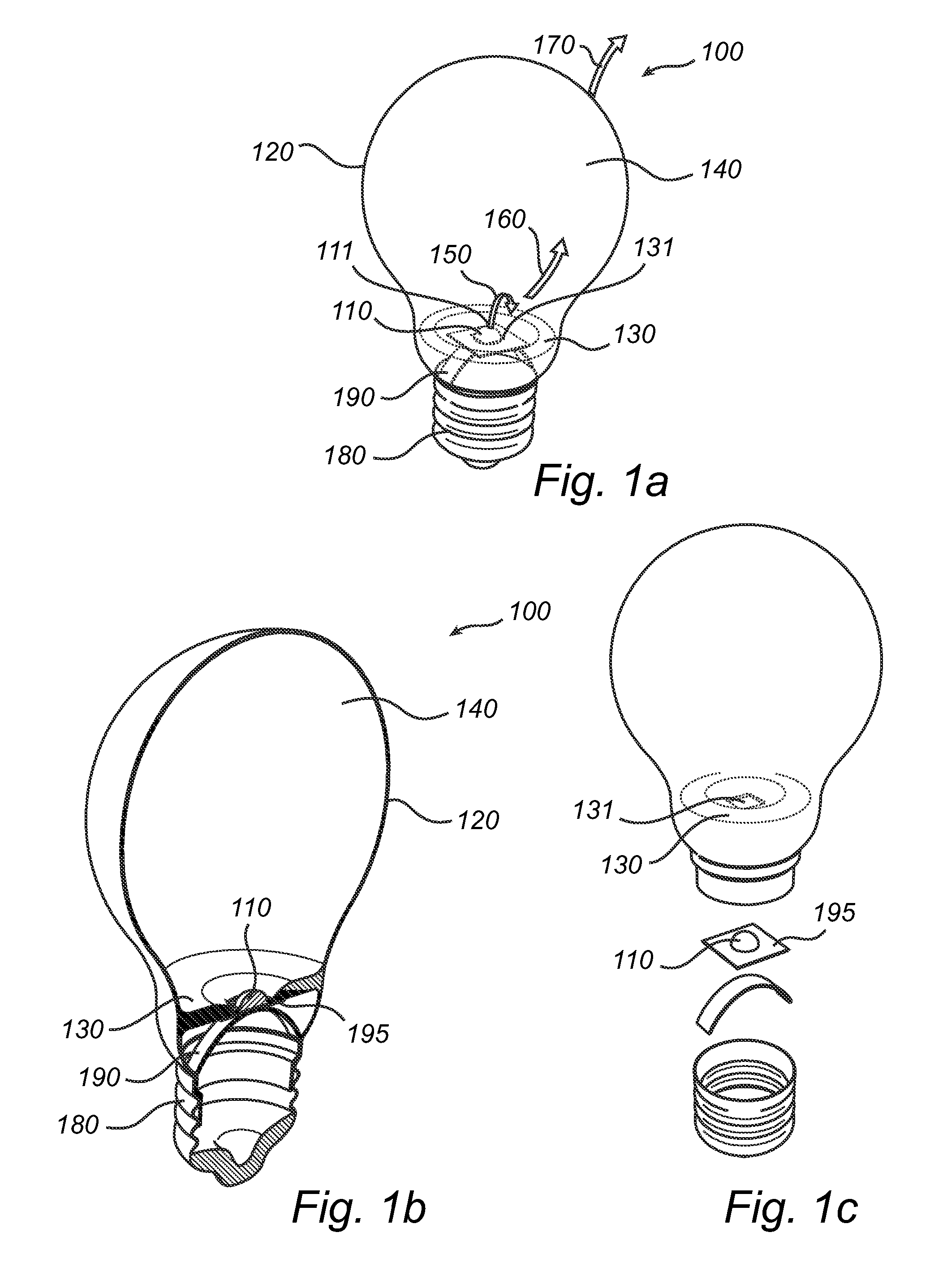
[0036]With reference to FIG. 1a-c, a first embodiment of the present invention is described.

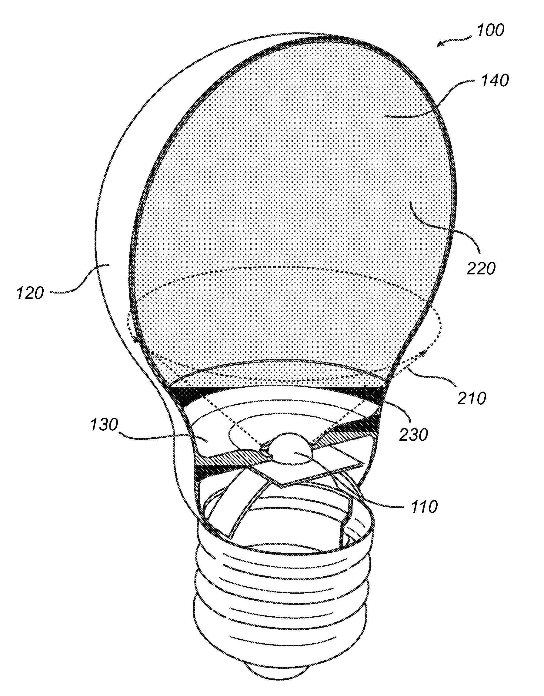
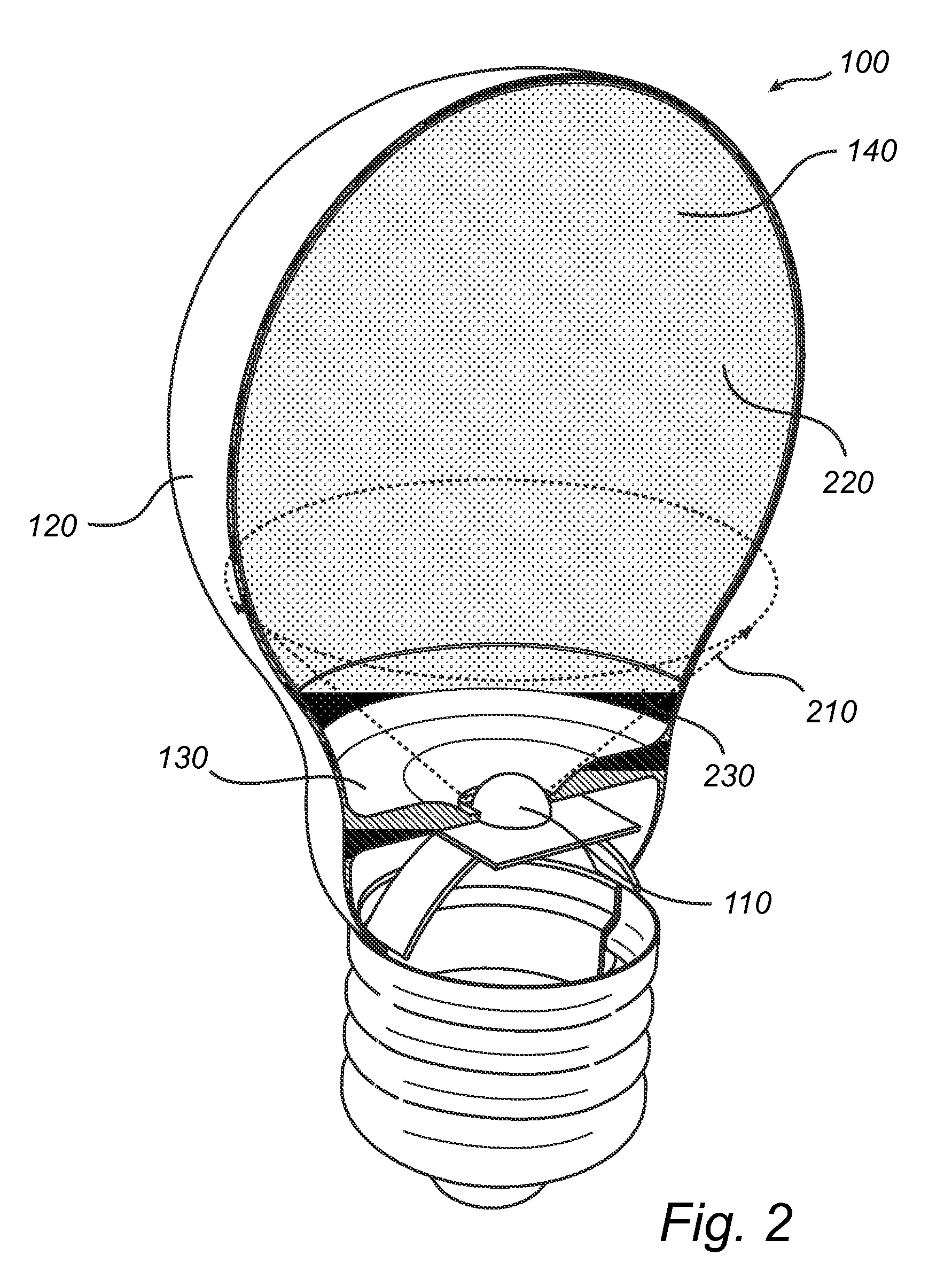
[0037]FIG. 1a shows an illumination device 100 according to an embodiment of the present invention. The illumination device 100 comprises a light source 110 arranged to generate light. In the present example, the light source 110 corresponds to a single LED 111 arranged on a printed circuit board (PCB) (not shown in FIG. 1a). Although FIG. 1a shows a single LED 111 to form the light source 110, a plurality of LEDs or LED packages may also be provided. Furthermore, the light source 110 may comprise one or more high-voltage (HV) LEDs. Even more advantageously, phase-shifted HV LEDs may be provided for preventing stroboscopic effects.

[0038]The illumination device 100 further comprises an envelope 120, which in FIG. 1a is bulb-shaped. However, virtually any other shape of the envelope 120 may be feasible.

[0039]In FIG. 1a, the illumination device 100 further comprises a thermally conducting carrie...


PUM


Abstract

An illumination device comprising a light source (110). The illumination device comprises a thermally conducting carrier (130) arranged to support the light source. Furthermore, the illumination device comprises an envelope (120), wherein the carrier and the envelope together form a single compartment (140) at least partially enclosing the light source. The carrier is arranged to transfer heat (160) away from the light source to the envelope, and the envelope is arranged to dissipate heat (170) away from the illumination device. The carrier and the envelope of the illumination device may further form a single integrated part.

Description

FIELD OF THE INVENTION[0001]The present invention relates to an illumination device and, in particular, to an illumination device suitable for use with a heat-sensitive light source.BACKGROUND OF THE INVENTION[0002]Light-emitting-diode (LED) lamps are known in the art. A LED lamp is a lamp that uses LEDs as the source of light. In such lamps, multiple diodes may be used, e.g. for increasing the output power of the lamp or for providing a white light. LED lamps may be used for a general lighting or even for a more specific lighting, as the colour and the output power of the LEDs may be tuned.[0003]Generally, a lamp or illumination device comprises a light source arranged to generate light, wherein the light source is mounted on, or at least connected to, a circuit board. The light source may be arranged within an encapsulating housing, usually having the shape of a bulb. In addition to provide a maximum output of light and / or a specific colour of light, the design of an illumination ...

Claims


Application Information

Patent Timeline
Patent Type & Authority Patents(United States)
IPC IPC(8): F21V29/00F21K99/00F21V29/506F21V3/00F21V29/85
CPCF21V29/506F21K9/232F21K9/61F21V29/86F21Y2101/00F21V3/02F21V3/04F21Y2115/10
Inventor MARINUS, ANTONIUS ADRIANUS MARIAGIELEN, VINCENT STEFAN DAVID STEFAN DAVIDBUKKEMS, PETER JOHANNES MARTINUS
Owner KONINKLIJKE PHILIPS ELECTRONICS NV
Learn More