Thermal engine for operation with noncombustible fuels

a fuel-based engine and non-combustible technology, applied in the field of engines, can solve problems such as global pollution and health associated problems, and achieve the effects of reducing the complexity of the expanded fluid control system, reducing the length of the engine, and reducing the radiation

Active Publication Date: 2016-11-22
ANTHONY MICHAEL
View PDF3 Cites 7 Cited by
  • Summary
  • Abstract
  • Description
  • Claims
  • Application Information

AI Technical Summary

Benefits of technology

The invention is a thermal engine that uses plastic components to reduce weight and cost. The engine has a cylinder block with multiple cylinders, a piston head, and a valve block all connected together. The engine operates at a low temperature and requires a flywheel to keep it running. The engine also includes a radiator to quickly cool the expanded fluid vapor and recycle it for reuse. The recycled fluid is held in the same passageways as the engine, minimizing the size of the engine and exposure to the atmosphere. The invention also provides a simplified design for the expansion fluid tank.

Problems solved by technology

The current prior art engines therefore rely on combustible fuels that cause global pollution and health associated problems.

Method used


Image

  • Thermal engine for operation with noncombustible fuels
  • Thermal engine for operation with noncombustible fuels
  • Thermal engine for operation with noncombustible fuels

Examples


first preferred embodiment

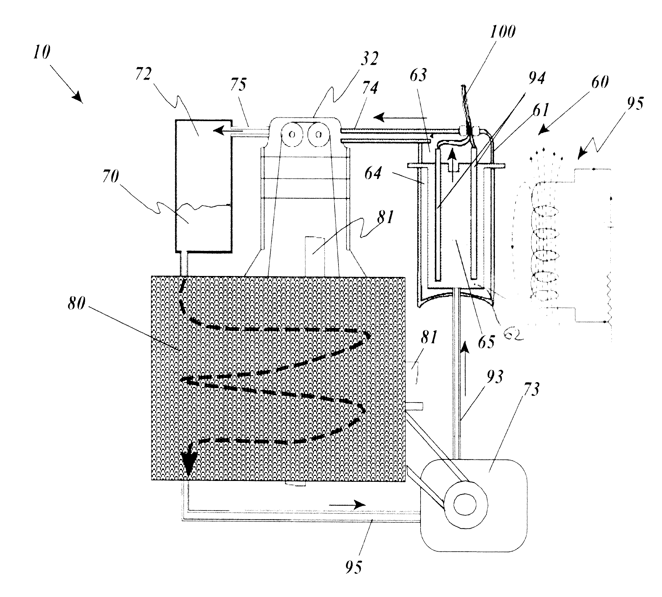
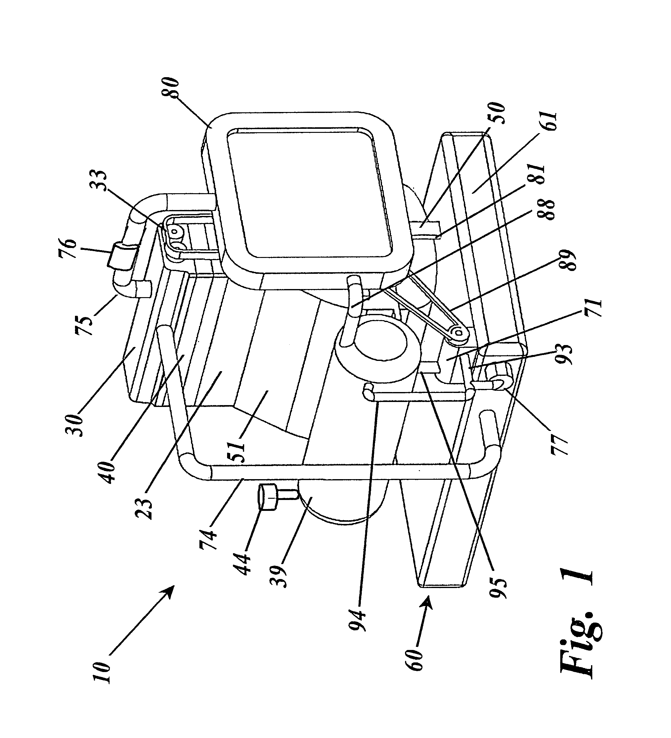
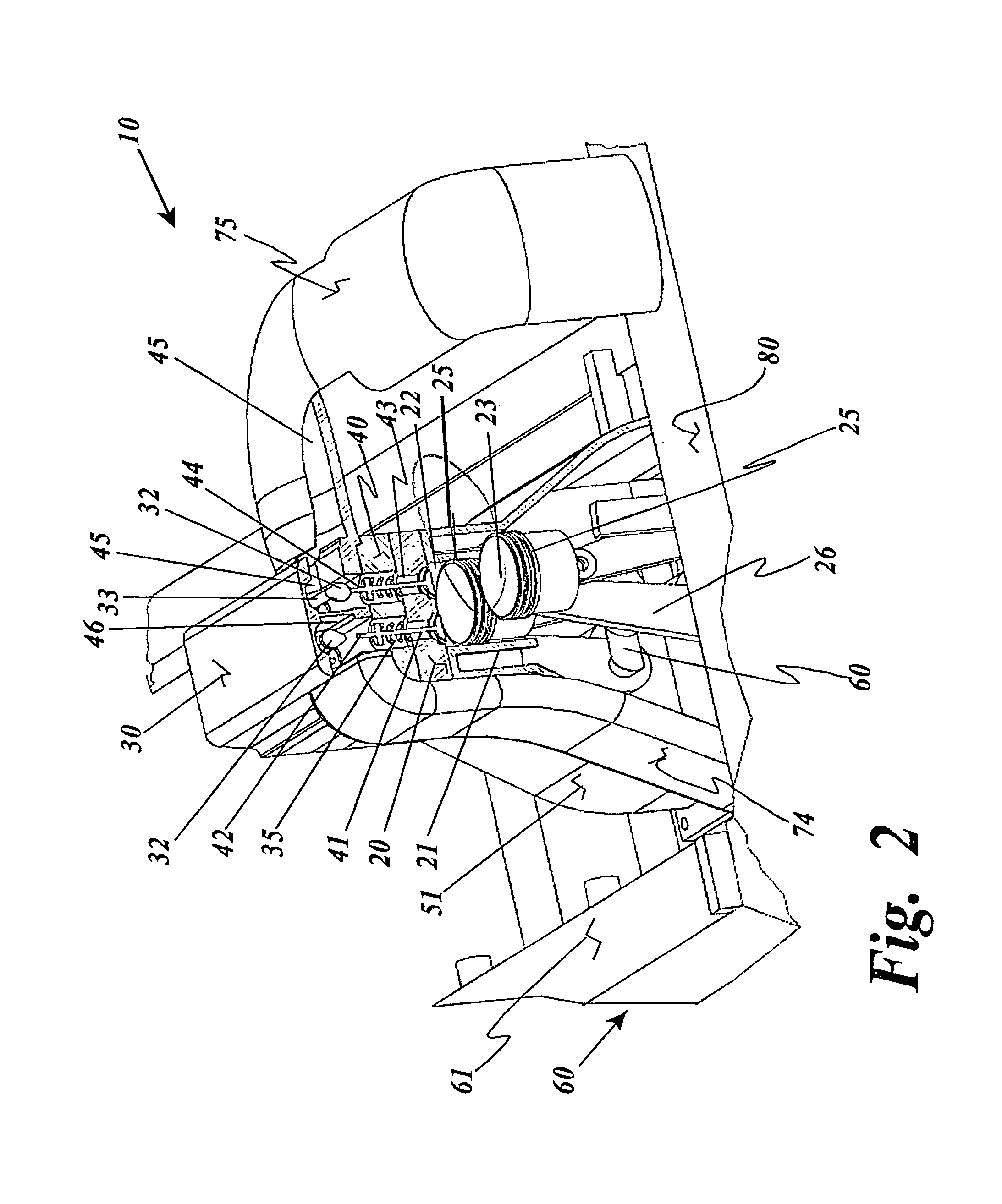
[0085]More specifically the present invention relates to a thermal engine 10 such as for powering a vehicle 200, including a cylinder 21 and a piston 24 having a piston head 23 and a piston crank 26 and an insulated thermal battery 60 including at least a thermal mass 62 such as a metal block for storing and retaining heat to cause expansion fluid 70 to expand inside the a cylinder expansion chamber 22 between the cylinder head 25 and the piston head 23 to drive a crankshaft 57.

[0086]Since the anticipated operating temperature of the thermal expansion fluid 70 depends on it boiling point, except for the thermal battery 60, the remaining thermal engine 10 can be constructed from durable materials such as aluminum and a suitable plastic material such as polypropylene or peek. In its most basic form, as mentioned above generally, the thermal engine 10 incorporates several conventional engine elements including valve cover 30 sealingly mated to a valve block 40 sealingly mated to an eng...


PUM


Abstract

A thermal engine includes a cylinder and piston and an insulated thermal battery including at least a thermal mass such as the engine block itself for storing and retaining heat to enhance or cause fluid expansion within the cylinder and drive the piston, the thermal battery optionally including an electrolyte chamber containing a thermal electrolyte for functioning as an electric thermal battery. Heat is stored in the thermal battery such as by activating electric resistance heating elements in the thermal mass. The stored heat either causes expansion of a non-combustible expansion fluid such as water or enhances the expansion of a combustible expansion fluid such as gasoline. Where the thermal battery is an electric thermal battery containing an electrolyte, the storage of heat also stores electricity which can be used to power an electric motor.

Description

FILING HISTORY[0001]This application is a continuation-in-part of application Ser. No. 12 / 380,626, filed on Mar. 2, 2009, now U.S. Pat. No. 8,186,160.BACKGROUND OF THE INVENTION[0002]1. Field of the Invention[0003]The present invention relates generally to the field of engines which convert heat into mechanical energy. More specifically the present invention relates to a thermal engine such as for powering a vehicle, including a cylinder and a piston having a piston head and a piston crank and an insulated thermal battery including at least a thermal mass such as a metal block for storing and retaining heat to cause expansion fluid to expand inside the a cylinder expansion chamber between the cylinder head and the piston head to drive a crankshaft.[0004]In its most basic form, as mentioned above generally, the thermal engine incorporates several conventional engine elements including engine valve block cover sealingly mated to an engine valve block sealingly mated to an engine block...

Claims


Application Information

Patent Timeline
IPC IPC(8): F01P1/00F01K15/00F02G1/043
CPCF02G1/043F01B17/04F01B29/06F01K21/02F02B5/00F02B53/02H01M10/399H01M14/00H01M2300/0048Y02E60/10Y02T10/12
Inventor ANTHONY, MICHAEL
Owner ANTHONY MICHAEL
Why Eureka
Try Eureka