Lighting apparatus with improved thermal insulation

Active Publication Date: 2016-11-08
CHM INDS
View PDF12 Cites 0 Cited by
  • Summary
  • Abstract
  • Description
  • Claims
  • Application Information

AI Technical Summary

Benefits of technology

The patent describes a lighting apparatus that includes a ballast housing, a lighting element housing, and a ventilation chamber between them. The ventilation chamber can include a heat dissipation pathway to divert heat away from the lighting element. The lighting element housing can have a vent and a filter to filter air. The ballast housing can have a heat shield and the lighting element housing can have a sealed housing or a cord grip for air tightness. The technical effects of the invention include improved heat dissipation, reduced air pollution, and better air flow.

Problems solved by technology

Lighting mechanisms include one or more lighting elements, and associated components, that produce large amounts of heat during operation.
As such, it has long been a challenge to create lighting mechanisms that incorporate the high-temperature lighting elements and associated operational components with the temperature-sensitive controls in a single unit.
For example, current single-unit lighting mechanisms oftentimes mount heat-sensitive controls directly adjacent to the high-temperature lighting element and / or fail to provide for adequate thermal insulation between the controls and the lighting element.
As such, the controls are often exposed to excessive temperatures; thus, the overall efficiency, reliability and useful life of the lighting mechanism is substantially reduced.

Method used


Image

  • Lighting apparatus with improved thermal insulation
  • Lighting apparatus with improved thermal insulation
  • Lighting apparatus with improved thermal insulation

Examples


Embodiment Construction

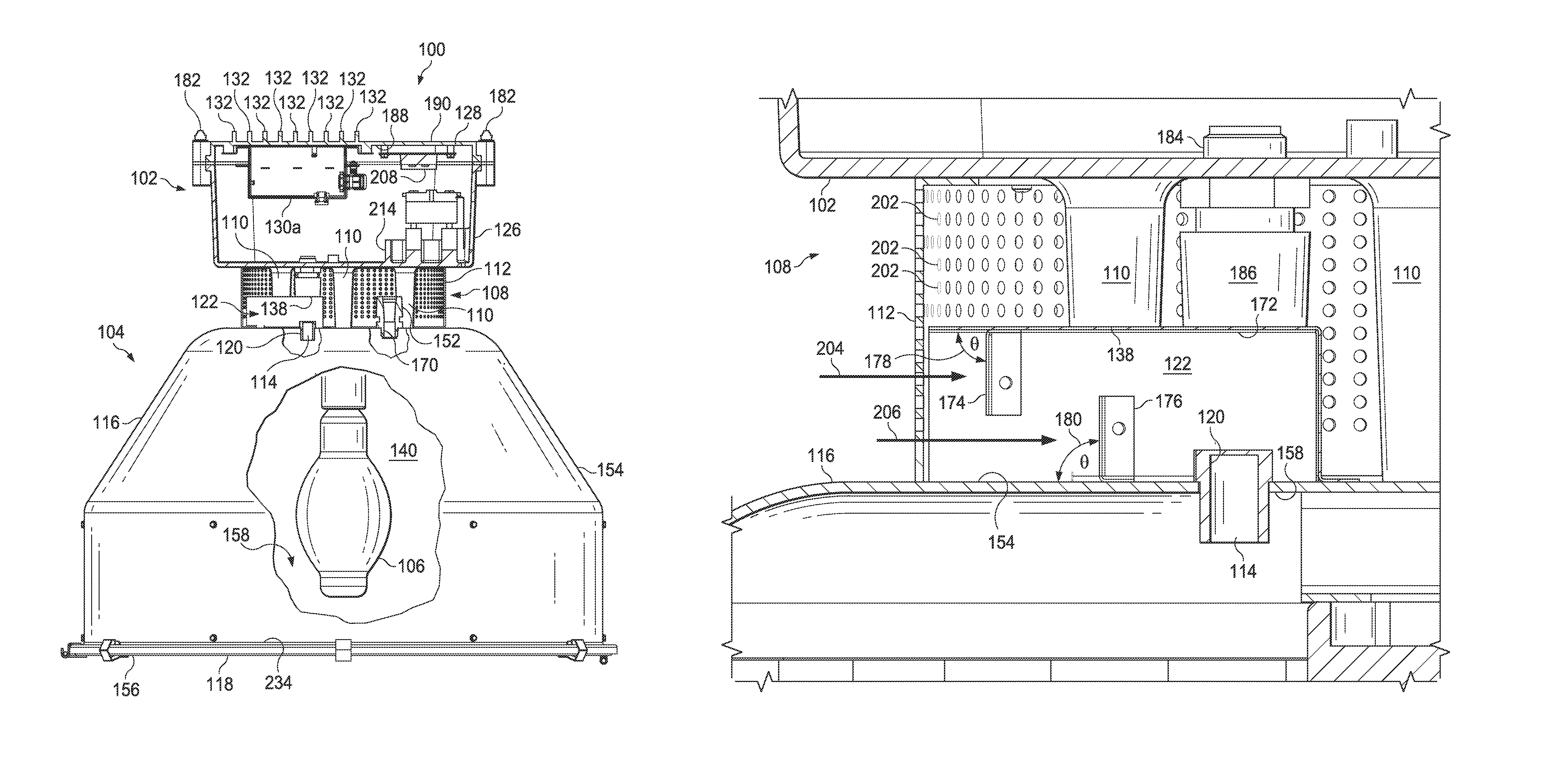
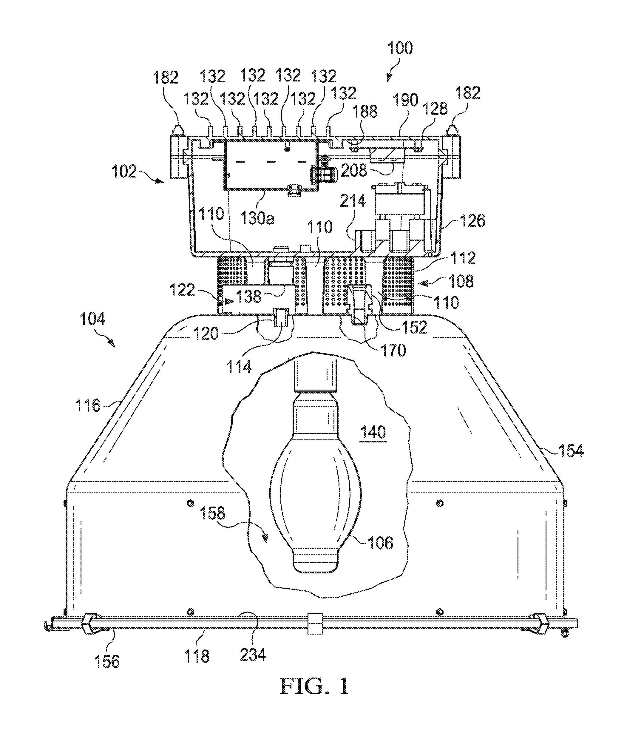
[0031]Referring to FIGS. 1 and 2, a lighting apparatus 100 is shown that includes a lighting element 106 and associated controls for operating the lighting element 106, such as, for example, a ballast 130a. The apparatus 100 thermally isolates temperature-sensitive components, such as the ballast 130a, from heat-producing elements, such as the lighting element 106, in order to protect the temperature-sensitive components and to increase the overall efficiency and useful life of the lighting apparatus 100.

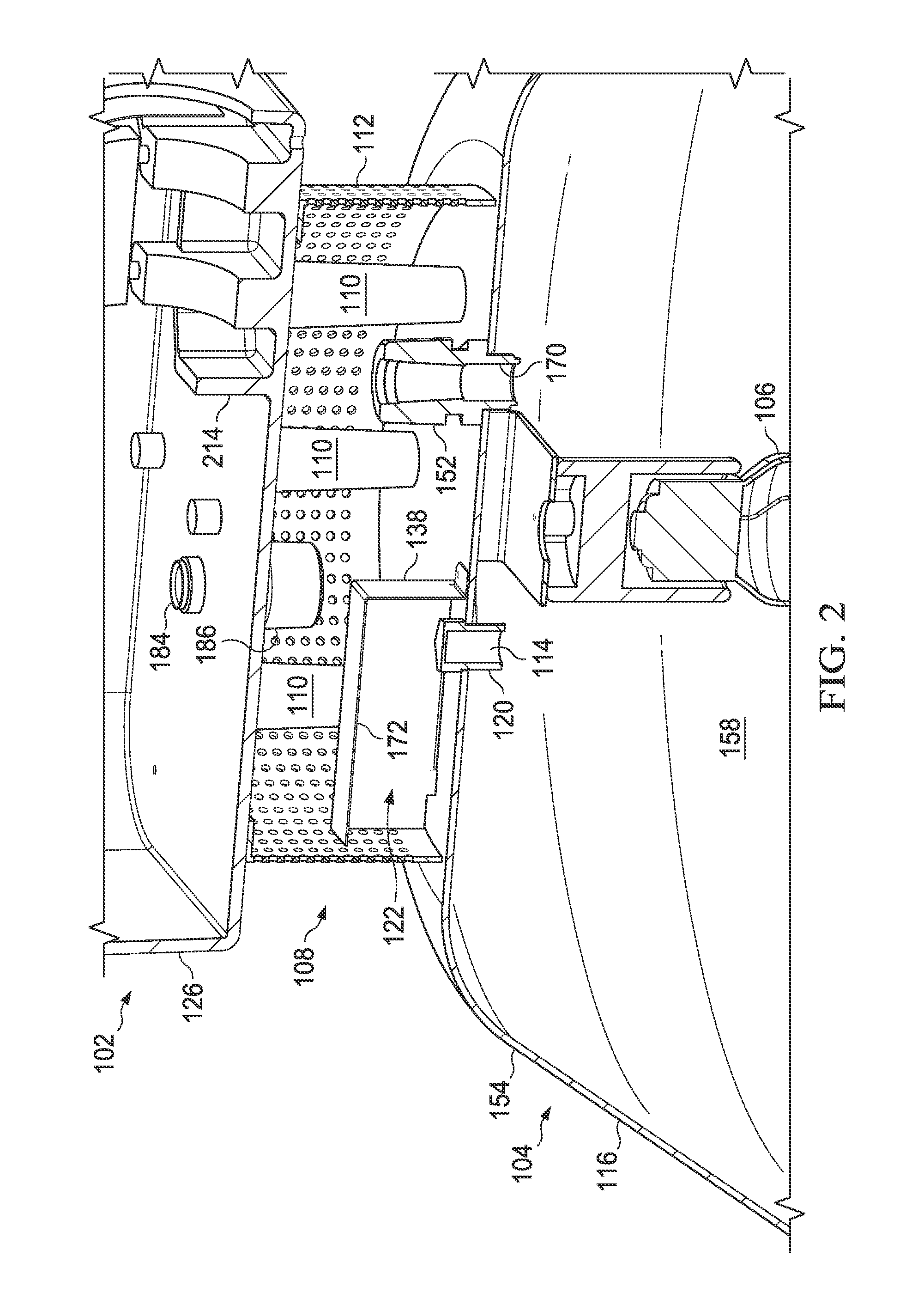
[0032]Referring specifically to FIG. 1, the apparatus 100 includes a lighting element housing 104, a ballast housing 102 and a ventilation chamber 108. The lighting element housing 104 is connected to and spaced from a ballast housing 102 by the ventilation chamber 108 and one or more spacers 110 located within the ventilation chamber 108. As discussed in more detail below, the ventilation chamber 108 acts to reduce and / or substantially eliminate overheating of the ballast housing 1...


PUM


Abstract

A lighting apparatus is described that may include a ballast housing, a lighting element housing and a ventilation chamber. The lighting element housing may include a lighting element. The ventilation chamber may be disposed between the ballast housing and the light element housing to maintain a predetermined distance between the ballast housing and the lighting element housing to reduce heat transferred from the lighting element to the ballast housing.

Description

TECHNICAL FIELD[0001]This disclosure relates to lighting apparatuses, and more particularly to high-efficiency lighting apparatuses with improved thermal insulation, and even more particularly to high-efficiency lighting apparatuses with improved thermal insulation for high mast applications.BACKGROUND OF THE DISCLOSURE[0002]Lighting mechanisms include one or more lighting elements, and associated components, that produce large amounts of heat during operation. Many lighting mechanisms, however, also require controls for the lighting elements, such as a capacitor, igniter and / or ballast, which are temperature sensitive and must remain at or below a specified working temperature to prevent damage to the controls, to maximize the overall efficiency of the lighting mechanism and to maximize the useful life of the lighting mechanism. As such, it has long been a challenge to create lighting mechanisms that incorporate the high-temperature lighting elements and associated operational comp...

Claims


Application Information

Patent Timeline
IPC IPC(8): F21V29/00H01J61/52F21V29/83F21V29/502
CPCF21V29/02H01J61/52F21V29/83F21V29/004F21V29/502F21V31/03F21S8/08F21V29/508
Inventor ENGBERG, SCOTT
Owner CHM INDS
Why Eureka
Try Eureka