Flat Knitting Machine, Knitting Program, and Method For Generating Knitting Program

Inactive Publication Date: 2008-07-17
SHIMA SEIKI MFG LTD
View PDF5 Cites 0 Cited by
  • Summary
  • Abstract
  • Description
  • Claims
  • Application Information

AI Technical Summary

Benefits of technology

[0014]In the present invention, the carriage accompanies the movable yarn guide in accordance with the control data for the movable yarn guide in the knitting program. Therefore, the position of the yarn carrier is controlled finely, and the yarn carrier is always kept at a suitable position relative to the yarn carrier. In the structure, it is possible to smoothly feed the yarn to the yarn carrier. Unlike the structure in which the yarn carrier pushes the movable yarn guide to move the movable yarn guide, the suitable distance between the yarn carrier and the movable yarn guide is maintained even during the movement of the movable yarn guide.
[0015]In the case where the carriage is provided with a plurality of accompanying means along the longitudinal direction of the needle bed, when one of the accompanying means accompanies the yarn carrier, and the other of the accompanying means accompanies the movable yarn guide, an interval corresponding to the accompanying means is formed between the yarn carrier and the movable yarn guide. The interval roughly corresponds to the interval between the cam systems for operating the needle bed. Thus, while supplying the yarn from the yarn carrier and knitting, it is possible to move the movable yarn guide while maintaining a predetermined interval from the yarn carrier to the movable yarn guide.
[0016]Depending on the position of releasing the accompaniment of the movable yarn guide, at the time of the next accompaniment of the movable yarn guide, it may become necessary to move the carriage only for the accompaniment of the movable yarn guide. This occurs when the stroke of the yarn carrier is decreased. When the accompaniment of the movable yarn guide is released in accordance with the preceding stroke, at the time of starting the next accompaniment, if the stroke of the carriage is determined without considering the position of the movable yarn guide, the accompaniment of the movable yarn guide may not be possible. Therefore, by determining the accompaniment release position of the movable yarn guide such that accompaniment can be started without excessive movement of the carriage at the time of next accompaniment of the movable yarn guide, the knitting efficiency does not decrease due to the accompaniment of the movable yarn guide.
[0017]For example, the control data for the movable yarn guide may be generated by a knit design apparatus. Alternatively, the control data for the movable yarn guide may be generated by the flat knitting machine. Since the control data for the yarn carrier is included in the knitting program conventionally, based on the control data for the yarn carrier, it is possible to generate the control data for the movable yarn guide simply.
[0017]For example, the control data for the movable yarn guide may be generated by a knit design apparatus. Alternatively, the control data for the movable yarn guide may be generated by the flat knitting machine. Since the control data for the yarn carrier is included in the knitting program conventionally, based on the control data for the yarn carrier, it is possible to generate the control data for the movable yarn guide simply.

Problems solved by technology

For example, when the yarn carrier pushes the movable yarn guide, the distance between the yarn carrier and one of the movable yarn guides is too small, and the distance between the yarn carrier and the other of the movable yarn guides is too large.
Further, until the yarn carrier contacts the movable yarn guide, though the movable yarn guides are positioned at substantially suitable positions, these positions are not always the optimum positions.
However, the range is too wide, and cannot be said as the suitable range.
In the case of Japanese Patent No. 2857840, while the yarn carrier accompanies the movable yarn guide, the distance between the yarn carrier and the movable yarn guide is too small.
Therefore, it is not possible to accompany the movable yarn guide with the yarn carrier, and perform knitting at the same time.

Method used


Image

  • Flat Knitting Machine, Knitting Program, and Method For Generating Knitting Program
  • Flat Knitting Machine, Knitting Program, and Method For Generating Knitting Program
  • Flat Knitting Machine, Knitting Program, and Method For Generating Knitting Program

Examples


Embodiment Construction

[0026]Hereinafter, embodiments in the most preferred form for carrying out the present invention will be described.

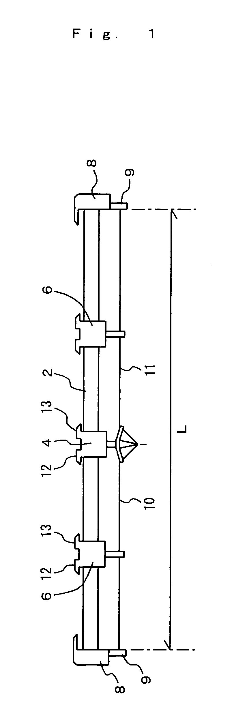
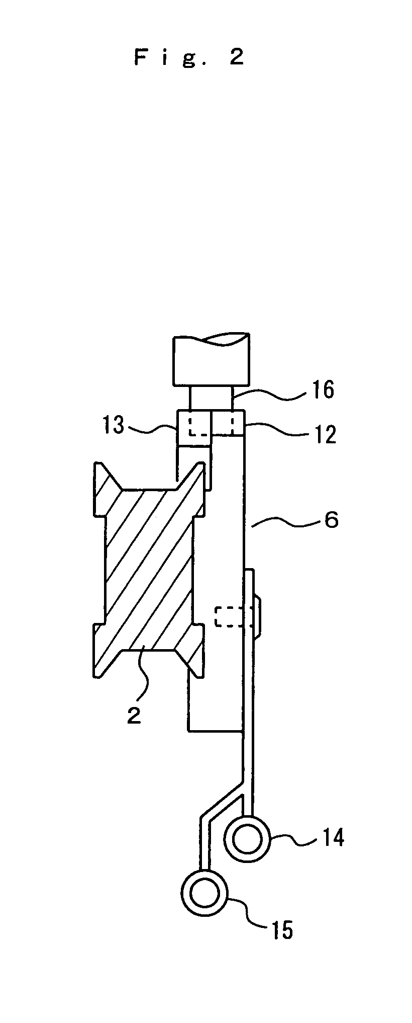
[0027]An embodiment and its modified embodiment will be described with reference to FIGS. 1 to 7. In the drawings, a reference numeral 2 denotes a yarn guide rail of a flat knitting machine. The yarn guide rail 2 supports a yarn carrier 4 and movable yarn guides 6 for feeding yarns 10, 11 to needles on needle beds such that the yarn carrier 4 and the movable yarn guides 6 are freely movable. Fixed yarn guides 9 are provided at rail ends 8.

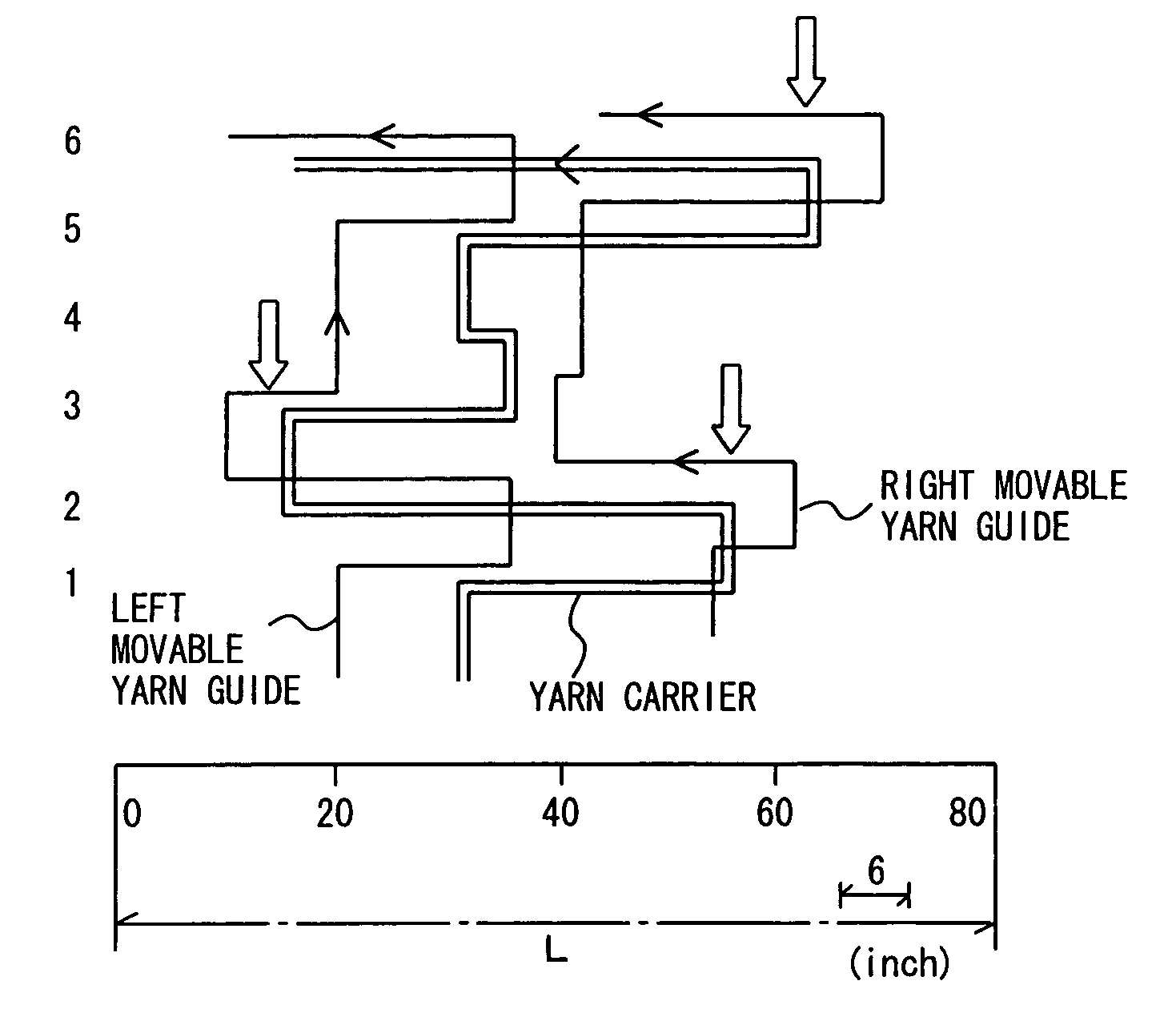
[0028]The movable yarn guides 6 guide the yarns between the fixed yarn guides 9 and the yarn carrier 4. Preferably, each of the movable yarn guides 6 is at substantially the central position between the yarn carrier 4 and the fixed yarn guide 9. The position of the movable yarn guide 6 is not limited to exactly the central position between the yarn carrier 4 and the fixed yarn guide 9, and may be deviated from the central position betw...


PUM


Abstract

A carriage allows accompaniment of a movable yarn guide as well as a yarn carrier, and accompanies the movable yarn guide with the yarn carrier. If there is a course where the accompaniment of the movable yarn guide is not possible, the movable yarn guide is accompanied beforehand to a position in a preceding course where the accompaniment becomes possible.

Description

TECHNICAL FIELD [0001]The present invention relates to control of a movable yarn guide in a flat knitting machine.BACKGROUND ART [0002]In a type of flat knitting machine, a movable yarn guide moves along a yarn guide rail, and guides a yarn fed to a yarn carrier. The movable yarn guide is required when the needle bed is long. The movable yarn guide is provided at a position between an end of the yarn guide rail and the yarn carrier for guiding the yarn supplied from a fixed yarn guide to the yarn carrier at a middle position between the fixed yarn guide and the yarn carrier. Thus, slack or swing of the yarn is prevented, and entanglement of yarns is prevented.[0003]According to the disclosure of Japanese Laid-Open Patent Publication No. 58-126351, a pair of left and right movable yarn guides are connected together, and a yarn carrier provided between the movable yarn guides are freely movable without interference with coupling means of the movable yarn guides. When the yarn carrier ...

Claims


Application Information

Patent Timeline
IPC IPC(8): D04B7/04G06F19/00D04B7/26D04B15/56D04B15/99
CPCD04B15/56D04B7/26
Inventor TOSHIAKI, MORITAHIDEYA, KAITOYOSHIYUKI, KOMURA
Owner SHIMA SEIKI MFG LTD
Why Eureka
Try Eureka