
Resin production method and resin production apparatus

a resin production method and resin technology, applied in the field of resin production methods, can solve the problems of large mold release force, pattern defects, and photolithography technology also coming close to a limi

Active Publication Date: 2016-10-25
CANON KK
View PDF28 Cites 7 Cited by
  • Summary
  • Abstract
  • Description
  • Claims
  • Application Information

AI Technical Summary

Benefits of technology

This method effectively reduces the mold release force, minimizing pattern defects and improving positioning accuracy by maintaining the mold and curable composition in contact until the desired tensile stress is achieved, facilitating precise pattern transfer.

Problems solved by technology

However, as the processing precision to be required is approaching a diffraction limit of exposure light, the photolithography technology is also coming close to a limit.
Incidentally, the nano-imprint method has various problems to be solved while being capable of forming a resin having a fine pattern.
One of the problems resides in that a force required for releasing a mold from a cured resin, that is, a mold release force is large.
When the mold release force is large, there arise problems such as the occurrence of pattern defects and the degradation in positioning accuracy caused by lifting up of a substrate from a stage.

Method used


Image

  • Resin production method and resin production apparatus
  • Resin production method and resin production apparatus
  • Resin production method and resin production apparatus

Examples


example 1

(1) Curable Composition (Radiation Curable Composition)

[0127]A curable composition (radiation curable composition) was prepared by mixing reagents shown below and a solvent.[0128][0129]trimethylolpropane triacrylate (manufactured by TOAGOSEI CO., LTD.): 100 parts[0130]Dar.1173 (manufactured by Ciba Japan): 3 parts[0131]2,2′-azobis-(N-butyl-2-methylpropioneamide) (trade name: VAm-110, manufactured by Wako Pure Chemical Industries, Ltd.): 15 parts[0132](Note 1) a polyfunctional (meth)acrylic compound having two or more methacryloyl groups[0133](Note 2) a gas generating agent producing gas with light

(2) Resin Production Method

[0134]First, the curable composition prepared as described above was applied to a silicon glass of 100 mm2. Then, a quartz glass (mold having no pattern) of 100 mm2 was held in parallel with the silicon glass, and the curable composition and the quartz glass were brought into contact with each other. In this case, the thickness of a film made of the curable compos...

example 2

[0135]A resin was produced by the same method as that of Example 1 except that the quartz glass was moved appropriately in a direction of increasing the relative distance between the silicon glass and the quartz glass so that a tensile stress became 0.177 N / mm2 in Example 1. Further, a mold release force was measured in the same way as in Example 1. Table 1 shows the results.

example 3

[0136]A resin was produced by the same method as that of Example 1 except that the quartz glass was moved appropriately in a direction of increasing the relative distance between the silicon glass and the quartz glass so that a tensile stress became 0.035 N / mm2 in Example 1. Further, a mold release force was measured in the same way as in Example 1. Table 1 shows the results.


PUM

PropertyMeasurementUnit
tensile stressaaaaaaaaaa
sizeaaaaaaaaaa
sizeaaaaaaaaaa

Abstract

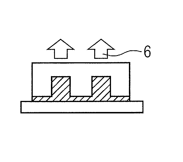
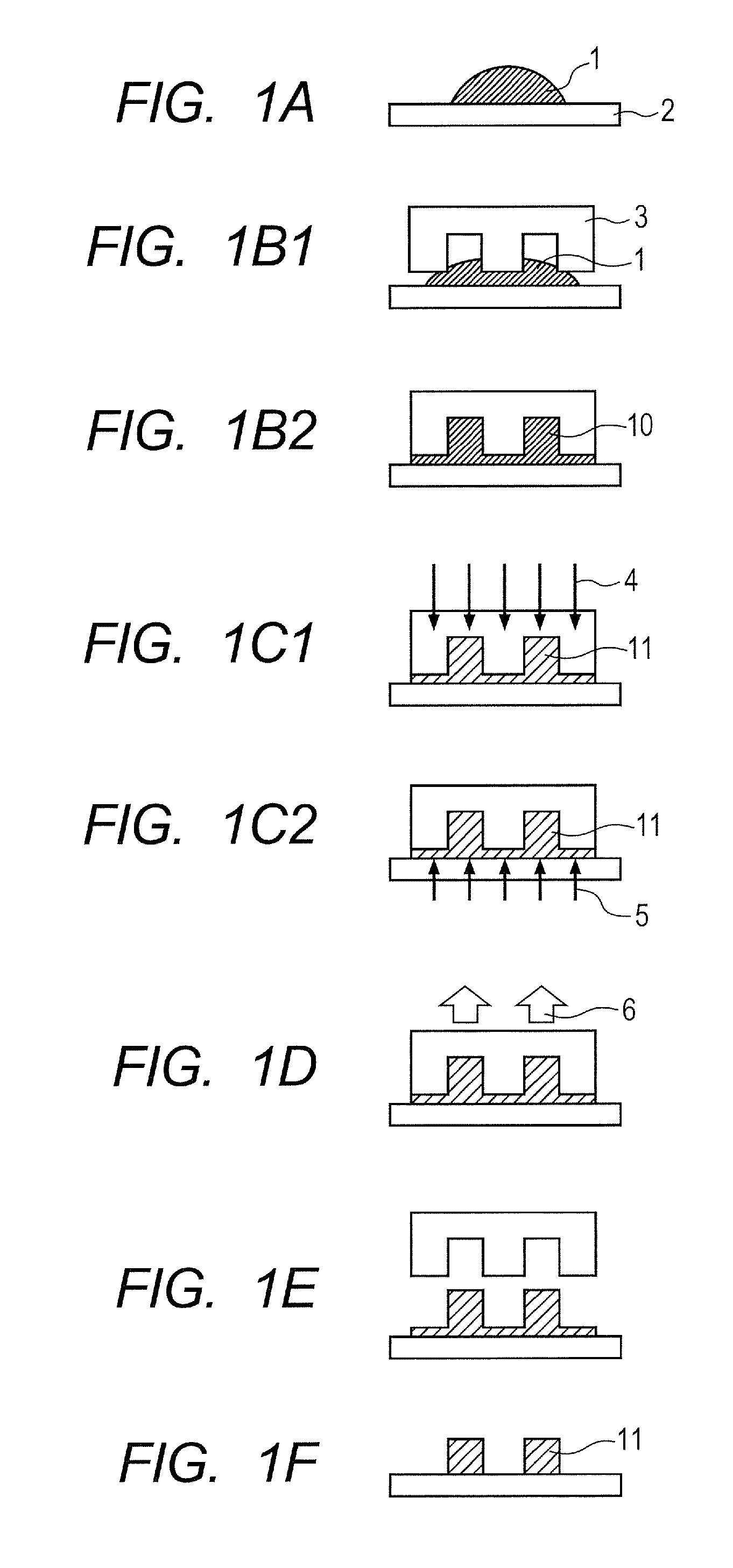
Provided is a resin production method in which a mold release force applied between a mold and a curable resin is reduced in a resin production method using a nano-imprint method. The resin production method includes an arrangement step of arranging a curable composition (1) on a substrate (2); a contacting step of bringing a mold (3) into contact with the curable composition (1); a curable composition curing step of curing the curable composition (1) by irradiating the curable composition (1) with a radiation or heating the curable composition (1) while keeping the curable composition (1) in contact with the mold (3); a tensile stress generation step of generating a tensile stress (6) in a direction of spacing the substrate (2) and the mold (3) away from each other to such a degree that the mold (3) and the curable composition (1) are not spaced away from each other when the curable composition (1) is cured; and a mold release step of releasing the curable composition (1) and the mold (3) from each other.

Description

TECHNICAL FIELD[0001]The present invention relates to a resin production method, in particular, a resin production method using a nano-imprint method, and a resin production apparatus used upon utilization of the production method.BACKGROUND ART[0002]Semiconductor integrated circuits are being miniaturized and integrated. As a pattern formation technology which is one of the fine processing technologies for realizing the miniaturization and the integration, there is given a photolithography process. In recent years, the precision of semiconductor integrated circuits has been increased through use of the photolithography process. However, as the processing precision to be required is approaching a diffraction limit of exposure light, the photolithography technology is also coming close to a limit. Then, as a method of realizing further miniaturization and higher precision, a nano-imprint method has been proposed. The nano-imprint method involves applying a resin to be cured with heat...

Claims


Application Information

Patent Timeline
Patent Type & Authority Patents(United States)
IPC IPC(8): B29C59/02G03F7/00G03F7/027B29K105/00
CPCB29C59/026G03F7/0002G03F7/027B29K2105/0002H01L21/027
Inventor IIDA, KENICHIITO, TOSHIKIMATSUFUJI, NAOKOSUZUKI, TATSUYA
Owner CANON KK
Learn More