
Method and system for recycling carbon dioxide from biomass gasification

a biomass gasification and carbon dioxide technology, applied in the direction of combustible gas catalytic treatment, combustible gas purification/modification, combustible gas production, etc., can solve the problems of complex process flow and large energy consumption, and achieve simple process flow, no oxygen consumption, and high material conversion

Inactive Publication Date: 2016-10-18
WUHAN KAIDI ENG TECH RES INST CO LTD
View PDF3 Cites 0 Cited by
  • Summary
  • Abstract
  • Description
  • Claims
  • Application Information

AI Technical Summary

Benefits of technology

The invention provides a method and system for recycling carbon dioxide from biomass gasification. The system has high material conversion and no oxygen consumption. The method has simple process flow and zero carbon dioxide emission. The carbon dioxide acts as a gasifying agent, no oxygen involved, which saves material consumption and improves conversion rate of materials. The invention has no special requirement on the particle size of materials, easy operation.

Problems solved by technology

Conventional methods and systems for gasification of biomass consume oxygen and natural gas, so that the CO2 conversion is low, the energy consumption is large, and the process flow is complex.

Method used


Image

  • Method and system for recycling carbon dioxide from biomass gasification
  • Method and system for recycling carbon dioxide from biomass gasification
  • Method and system for recycling carbon dioxide from biomass gasification

Examples


Embodiment Construction

[0037]Technical solution of the invention is illustrated with detailed embodiments hereinbelow, the embodiments, however, should not be explained as limitation of the protection range of the invention.

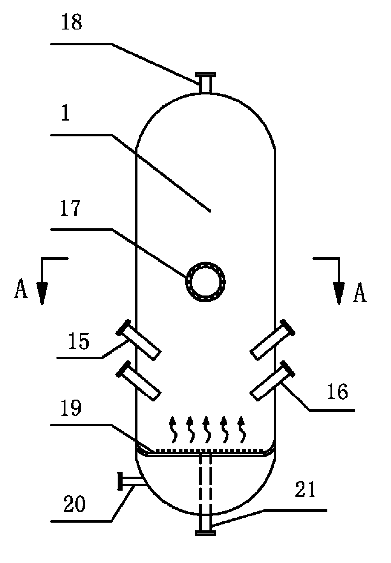
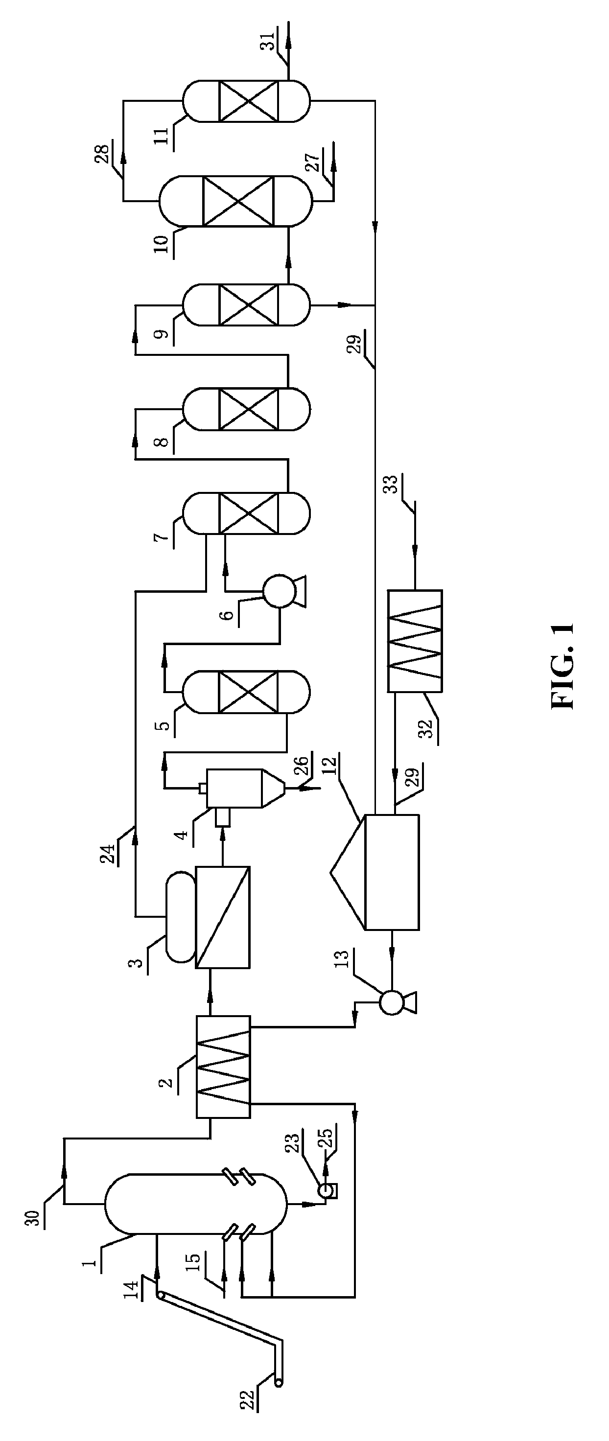
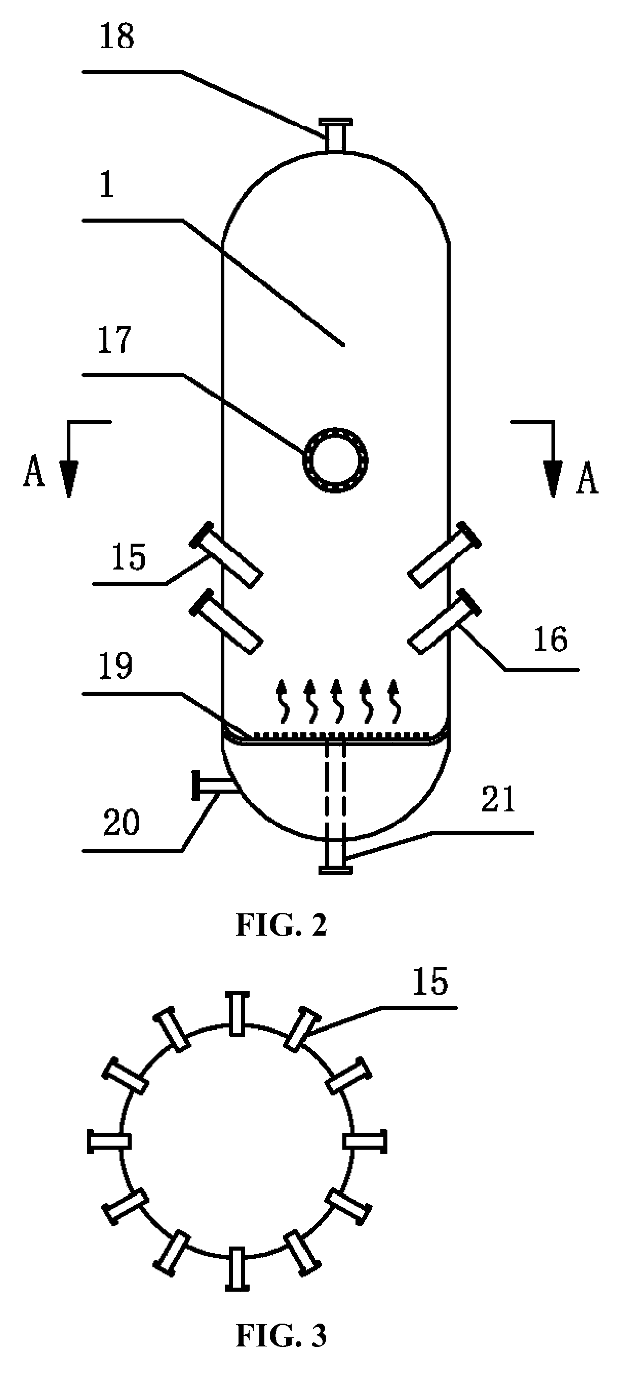
[0038]FIG. 1 is a schematic diagram of a system for recycling carbon dioxide from biomass gasification of the invention in the absence of oxygen. The system comprises a gasifier 1, a waste heat exchanger 2, a waste heat boiler 3, a cyclone separator 4, a gas scrubber 5, a compressor 6, a shift reactor 7, a desulfurizing tower 8, a first decarburizing tower 9, a synthesizing tower 10, and a second decarburizing tower 11. The gasifier 1 comprises a syngas outlet 18 at the top, a slag discharging outlet 21 at the bottom, and a feed inlet 17 in the middle of the external wall of the gasifier. The feed inlet is connected to a feeding device 22. An air distributor 19 is disposed in a lower part of the chamber of the gasifier 1. The wall of the gasifier above the air distributor 19 comprises ...


PUM

PropertyMeasurementUnit
temperatureaaaaaaaaaa
outlet temperatureaaaaaaaaaa

Abstract

A method for recycling carbon dioxide from biomass gasification. The method includes: 1) employing carbon dioxide as a gasifying agent, allowing the carbon dioxide to gasify biomass to yield syngas; 2) cooling the syngas; 3) introduced cooled syngas to a cyclone separator and a gas scrubber for dust removal and purification; 4) allowing purified syngas in 3) to react with the vapor to modify a ratio of hydrogen to carbon monoxide of the syngas; 5) desulfurizing modified syngas to remove H2S and COS therein; 6) decarburizing desulfurized syngas to separate carbon dioxide therein; 7) introducing desulfurized and decarburized syngas to a synthesizing tower to yield oil products and exhaust gas including carbon dioxide; 8) decarburizing the exhaust gas including carbon dioxide and separating the carbon dioxide; and 9) introducing the carbon dioxide separated in 6) and 8) to 1) as the gasifying agent for gasification.

Description

CROSS-REFERENCE TO RELATED APPLICATIONS[0001]This application is a continuation-in-part of International Patent Application No. PCT / CN2013 / 079230 with an international filing date of Jul. 11, 2013, designating the United States, now pending, and further claims priority benefits to Chinese Patent Application No. 201210282152.6 filed Aug. 9, 2012. The contents of all of the aforementioned applications, including any intervening amendments thereto, are incorporated herein by reference.BACKGROUND OF THE INVENTION[0002]1. Field of the Invention[0003]The invention relates to a method and system for recycling carbon dioxide from biomass gasification.[0004]2. Description of the Related Art[0005]Conventional methods and systems for gasification of biomass consume oxygen and natural gas, so that the CO2 conversion is low, the energy consumption is large, and the process flow is complex.SUMMARY OF THE INVENTION[0006]In view of the above-described problems, it is one objective of the invention ...

Claims


Application Information

Patent Timeline
Patent Type & Authority Patents(United States)
IPC IPC(8): C10J3/72C10K1/02C10K1/00C10K3/04C10G2/00C10J3/48
CPCC10J3/72C10G2/32C10J3/482C10K1/004C10K1/02C10K3/04C10G2300/1011C10J2200/15C10J2300/0916C10J2300/0969C10J2300/1238C10J2300/1659C10J2300/1693C10J2300/1815C10J2300/1861C10J2300/1884C10J2300/1892Y02E50/32Y02P20/129Y02P20/134Y02P20/145Y02P30/20C10G2/34C10J2300/123C10J2300/1269C10J2300/1292C10K1/026C10K1/08Y02E50/30Y02P20/133C10J3/00C10K3/00C10J3/82
Inventor ZHANG, YANFENGZHANG, LIANGXIA, MINGGUILIU, WENYAN
Owner WUHAN KAIDI ENG TECH RES INST CO LTD
Learn More