
Breather apparatus for internal combustion engine for vehicle

a technology for internal combustion engines and breathers, which is applied in the direction of combustion-air/fuel-air treatment, machines/engines, fuel air intakes, etc., can solve the problems that the separation of gas and liquid for separating liquid components from the blow-by gas may not be performed in the breather chamber

Active Publication Date: 2016-09-27
HONDA MOTOR CO LTD
View PDF6 Cites 2 Cited by
  • Summary
  • Abstract
  • Description
  • Claims
  • Application Information

AI Technical Summary

Benefits of technology

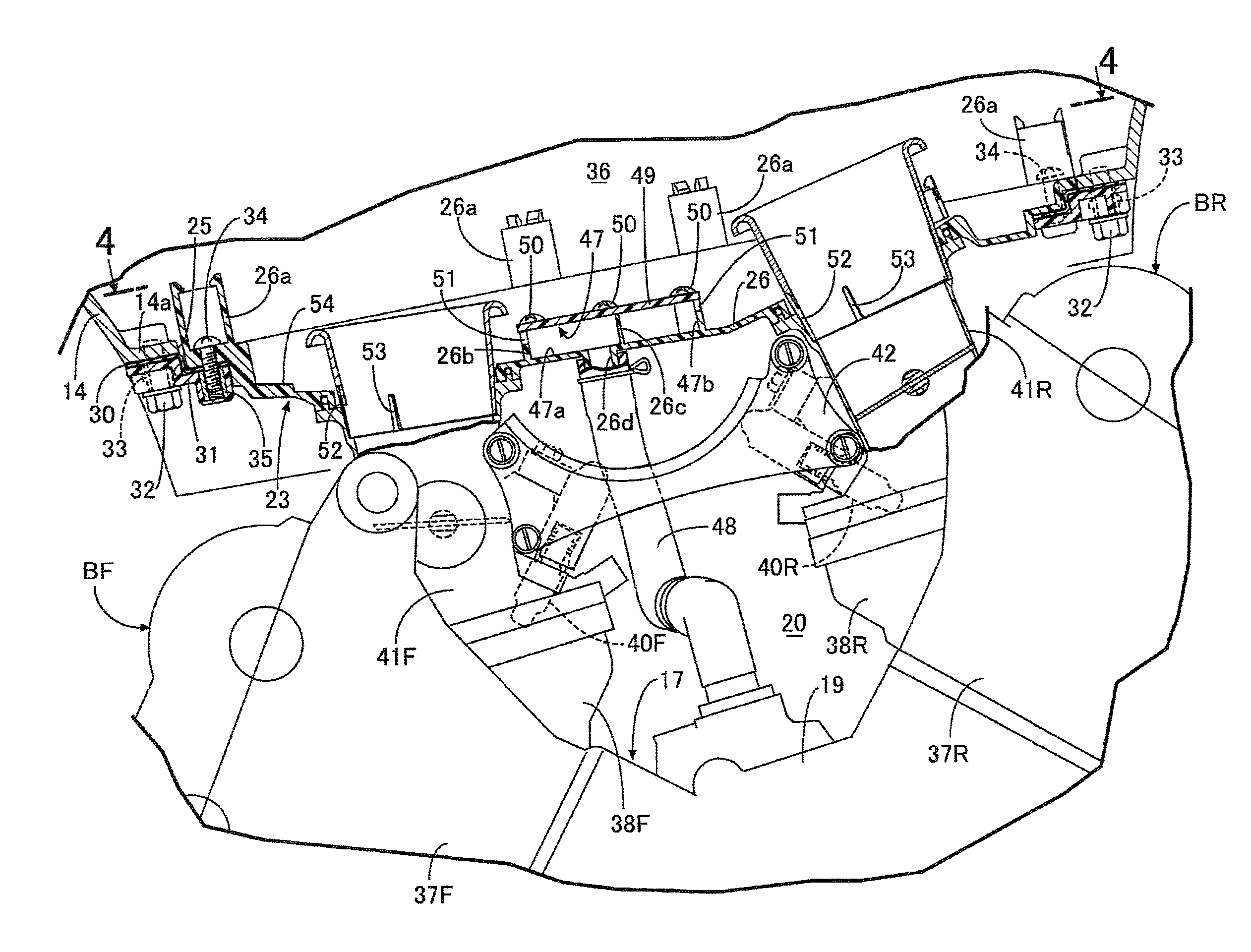
This patent describes a breather apparatus for an internal combustion engine in a vehicle. The invention aims to accelerate the separation of gas and liquid in a breather chamber formed in an air cleaner. The apparatus includes a U-shaped flow path and a guide projection for guiding liquid components from the breather chamber into the air cleaner. The breather chamber is formed by a bottom plate and a lid member, which are fixed together using a fixing member. The invention allows for a compact and cost-effective breather apparatus to be formed in the air cleaner.

Problems solved by technology

The separation of gas and liquid for separating liquid components from the blow-by gas may not be performed sufficiently in the breather chamber.

Method used


Image

  • Breather apparatus for internal combustion engine for vehicle
  • Breather apparatus for internal combustion engine for vehicle
  • Breather apparatus for internal combustion engine for vehicle

Examples


Embodiment Construction

[0030]An embodiment of the present invention is described with reference to the drawings. It is to be noted that, in the following description, forward and rearward, upward and downward, and leftward and rightward directions coincide with directions as viewed from a rider who rides on a motorcycle.

[0031]Referring to FIG. 1, part of a vehicle body frame F of a motorcycle which is a vehicle includes a head pipe 13 which supports a front fork 11 supporting a front wheel WF for rotation, and a steering handlebar 12 for steering operation, and a main frame 14 extending rearwardly downwardly from the head pipe 13. An engine main body 17 of a V-type internal combustion engine E configured, for example, with four cylinders is incorporated in the main frame 14.

[0032]Referring also to FIG. 2, the engine main body 17 has a crankcase 19 which supports a crankshaft 18, which extends in a vehicle widthwise direction, for rotation thereon, and a pair of banks, namely, a front bank BF and a rear ba...


PUM


Abstract

A breather apparatus for an internal combustion engine for a vehicle in which an air cleaner is disposed above a crankcase. A breather tube is provided for guiding blow-by gas exhausted from the crankcase. The breather tube is coupled with a breather chamber formed in the air cleaner to separate gas and liquid in the breather chamber in the air cleaner. An upstream side flow path, coupled to the breather tube, and a downstream side flow path, continuously extending in a substantially U-shape to the upstream side flow path, are formed in the breather chamber.

Description

CROSS-REFERENCE TO RELATED APPLICATIONS[0001]The present application claims priority under 35 USC 119 to Japanese Patent Application No. 2014-064782 filed Mar. 26, 2014 the entire contents of which are hereby incorporated by reference.BACKGROUND OF THE INVENTION[0002]1. Field of the Invention[0003]The present invention relates to a breather apparatus for an internal combustion engine in which an air cleaner is disposed above a crankcase which configures part of an engine main body incorporated in a vehicle body frame and supports a crankshaft for rotation, and a breather tube for guiding blow-by gas exhausted from the crankcase is coupled with a breather chamber formed in the air cleaner.[0004]2. Description of Background Art[0005]A breather apparatus is described in Japanese Patent No. 4732325.[0006]However, in the breather apparatus disclosed in Japanese Patent No. 4732325, the breather chamber in the air cleaner is formed as a single chamber. The separation of gas and liquid for ...

Claims


Application Information

Patent Timeline
Patent Type & Authority Patents(United States)
IPC IPC(8): F02B25/06F02M25/06F02M35/16F01M13/00F01M13/04F02M35/10F02M35/04
CPCF02M35/048F02M35/10222F02M35/162F01M13/00F01M13/04F01M13/0405F02M25/06F01M2013/005F01M2013/0461Y02T10/121Y02T10/12
Inventor KONTANI, MASAHIROMAHIRA, HIROSHI
Owner HONDA MOTOR CO LTD
Learn More