
Hydraulic drive

a technology of hydraulic drive and torque control, applied in the direction of gearing control, applications, couplings, etc., can solve the problems of low torque control, high cost, and closed circuit, and achieve the effect of good torque control, simple structure and flexible flexibility

Active Publication Date: 2016-09-20
LEIBHERR HYDRAULIKBAGGER GMBH
View PDF7 Cites 2 Cited by
  • Summary
  • Abstract
  • Description
  • Claims
  • Application Information

AI Technical Summary

Benefits of technology

The present invention provides a simpler, more flexible, and cost-effective hydraulic drive with good torque control. This is achieved by a hydraulic drive that allows for separate control of pressure at different connectors of the motor. The use of pressure reducing valves further simplifies the control of the motor. The invention can be used in various working equipment and allows for torque control of different components.

Problems solved by technology

The disadvantages of an open circuit are in this respect the complicated priority switching, the numerous valves and logic systems which are required for the control and the lack of a precise torque control.
The disadvantages of a system having a closed circuit are in particular the high costs since here a separate hydraulic pump has to be provided for each hydraulic motor.

Method used


Image

  • Hydraulic drive
  • Hydraulic drive

Examples


Embodiment Construction

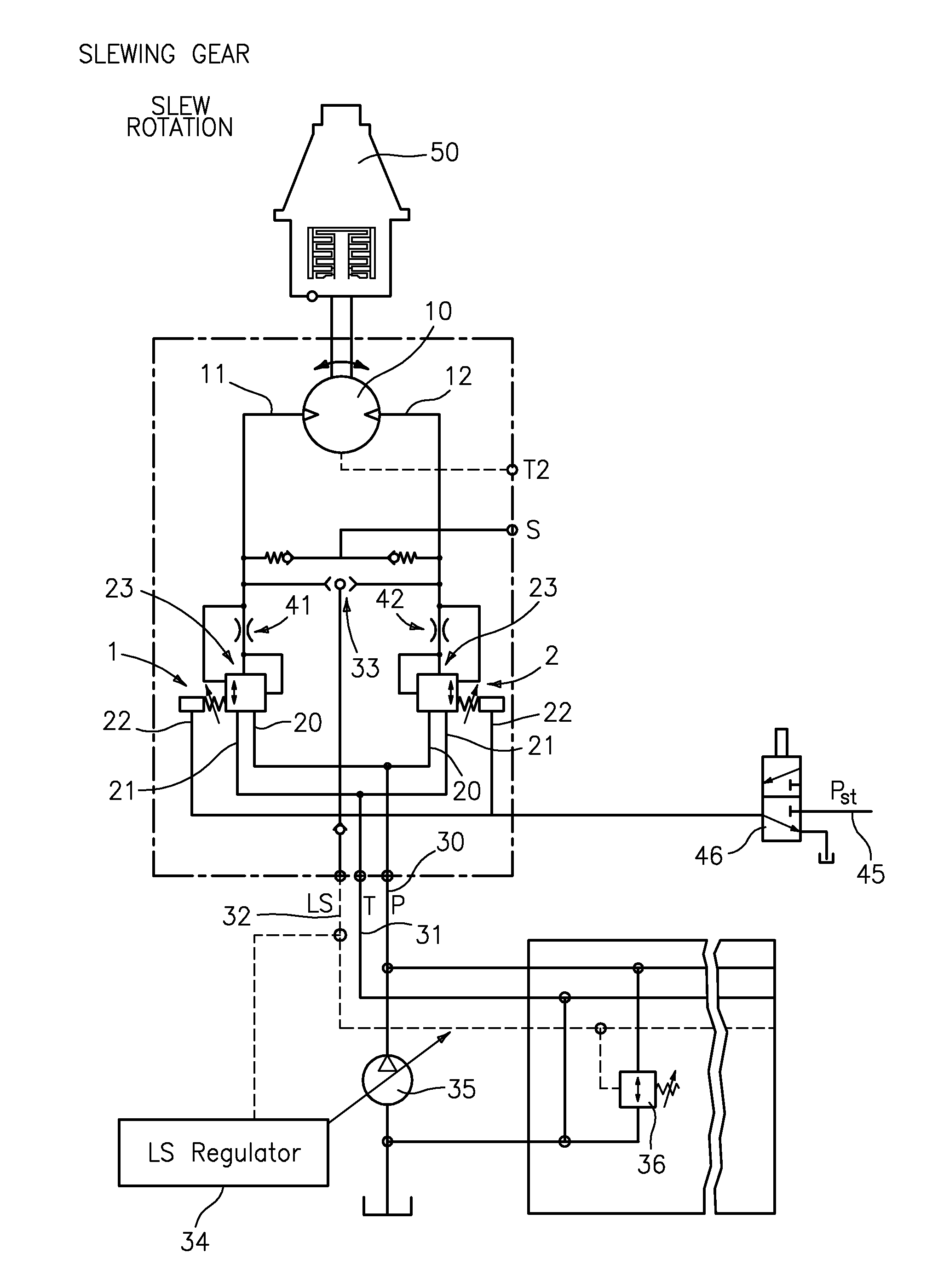
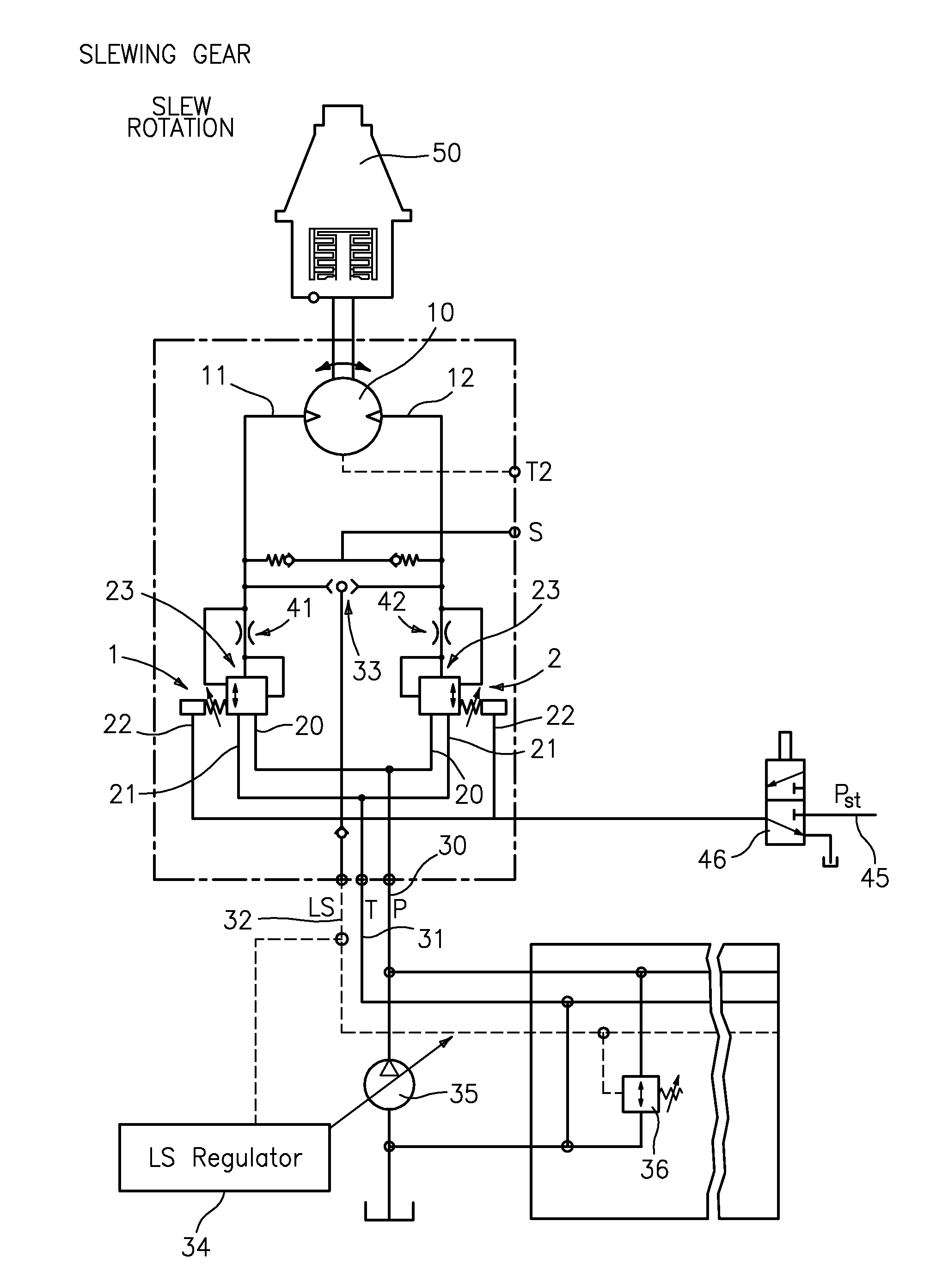
[0019]FIG. 1 shows an embodiment of the hydraulic drive in accordance with the invention comprising a hydraulic motor 10 which includes a first hydraulic connector 11 and a second hydraulic connector 12. The hydraulic motor is a fixed displacement motor having two directions of rotation. The hydraulic motor 10 is driven in this connection in that a pressure difference is applied between the first hydraulic connector and the second hydraulic connector, with the rotary movement of the hydraulic motor being determined by the quantity of hydraulic fluid flowing through the hydraulic motor and its displacement volume.

[0020]In accordance with the invention, the pressure applied at the first hydraulic connector 11 of the hydraulic motor 10 and the pressure applied at the second hydraulic connector 12 of the hydraulic motor 10 can now be set separately. For this purpose, a first pressure reducing valve 1 and a second pressure reducing valve 2 are provided, with the output 23 of the first pr...


PUM


Abstract

The present invention relates to a hydraulic drive which comprises a hydraulic motor having a first hydraulic connector and a second hydraulic connector, wherein the pressure applied at the first hydraulic connector of the hydraulic motor and the pressure applied at the second hydraulic connector of the hydraulic motor are each separately adjustable.

Description

BACKGROUND OF THE INVENTION[0001]The present invention relates to a hydraulic drive comprising a hydraulic motor which includes a first hydraulic connector and a second hydraulic connector. Such a hydraulic motor converts hydraulic energy into mechanical energy and is driven in that a pressure difference is applied between the first hydraulic connector and the second hydraulic connector of the hydraulic motor, whereby hydraulic fluid flows through the hydraulic motor. The rotary movement generated by the hydraulic motor is then determined by the displacement volume of the hydraulic motor and by the quantity of the hydraulic fluid flowing through the hydraulic motor.[0002]Previously, essentially the control in an open circuit and the control in a closed circuit have been known for the operation of hydraulic motors. In an open circuit, one of the two hydraulic connectors has pressure applied via a control valve, whereas the other connector is subject to return pressure. A directional ...

Claims


Application Information

Patent Timeline
Patent Type & Authority Patents(United States)
IPC IPC(8): F15B11/05E02F9/22F16H61/4017F16H61/4035F16H61/4026E02F9/12F16H59/68
CPCF16H61/4026E02F9/123E02F9/2228E02F9/2235E02F9/2296F15B11/05F16H61/4017F16H61/4035F15B2211/20546F15B2211/253F15B2211/40561F15B2211/4159F15B2211/428F15B2211/6054F15B2211/7058F16H2059/6861Y10T137/86493
Inventor MEIER, SIMONREISCH, THOMAS
Owner LEIBHERR HYDRAULIKBAGGER GMBH
Learn More