
Insulated wire, electrical equipment, and method of producing an insulated wire

a technology of insulated wires and insulated conductors, which is applied in the direction of insulated conductors/cables, cables, cables, etc., can solve the problems of low voltage decay due to connection cables, high steep voltage rise, and output pulses due to high-speed switching devices such as igbt, and achieve excellent resistance to partial discharge

Active Publication Date: 2016-09-13
ESSEX FURUKAWA MAGNET WIRE LLC
View PDF52 Cites 2 Cited by
  • Summary
  • Abstract
  • Description
  • Claims
  • Application Information

AI Technical Summary

Benefits of technology

[0032]According to the present invention, an insulated wire having excellent resistance to partial discharge, partial discharge inception voltage, flexibility and heat resistance can be provided. Further, an insulated wire having excellent characteristics such as described above can be produced.
[0033]Other and further features and advantages of the invention will appear more fully from the following description, appropriately referring to the accompanying drawings.

Problems solved by technology

In particular, an output pulse occurred due to a high-speed switching device, such as an IGBT, is high in steep voltage rise.
Accordingly, even if a connection cable is short, the surge voltage is high, and voltage decay due to the connection cable is also low.
However, these insulated wires having an insulating film containing particles have a problem that a partial discharge inception voltage is decreased, or flexibility of a coating film is decreased.
However, when the thickness of the insulating layer is increased, the resultant insulated wire becomes thicker, and as a result, size enlargement of electrical equipments is brought about.
Therefore, increasing the thickness of the insulating layer leads to a decrease in the space factor, and this is not desirable when the required performance is taken into consideration.
Furthermore, in practice, a resin having a low relative dielectric constant cannot always be selected necessarily when other properties that are required for the insulating layer (heat resistance, solvent resistance, flexibility and the like) are taken into consideration.
However, since such a foamed wire has a low heat resistant temperature of the coating film and poor scratch resistance, it is not satisfactory from this point of view.

Method used


Image

  • Insulated wire, electrical equipment, and method of producing an insulated wire
  • Insulated wire, electrical equipment, and method of producing an insulated wire

Examples


example 1

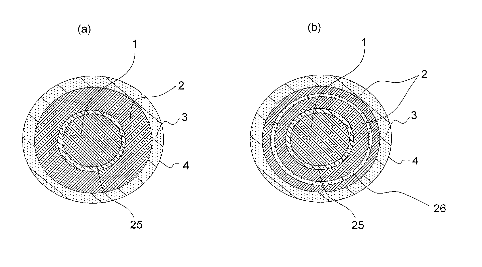
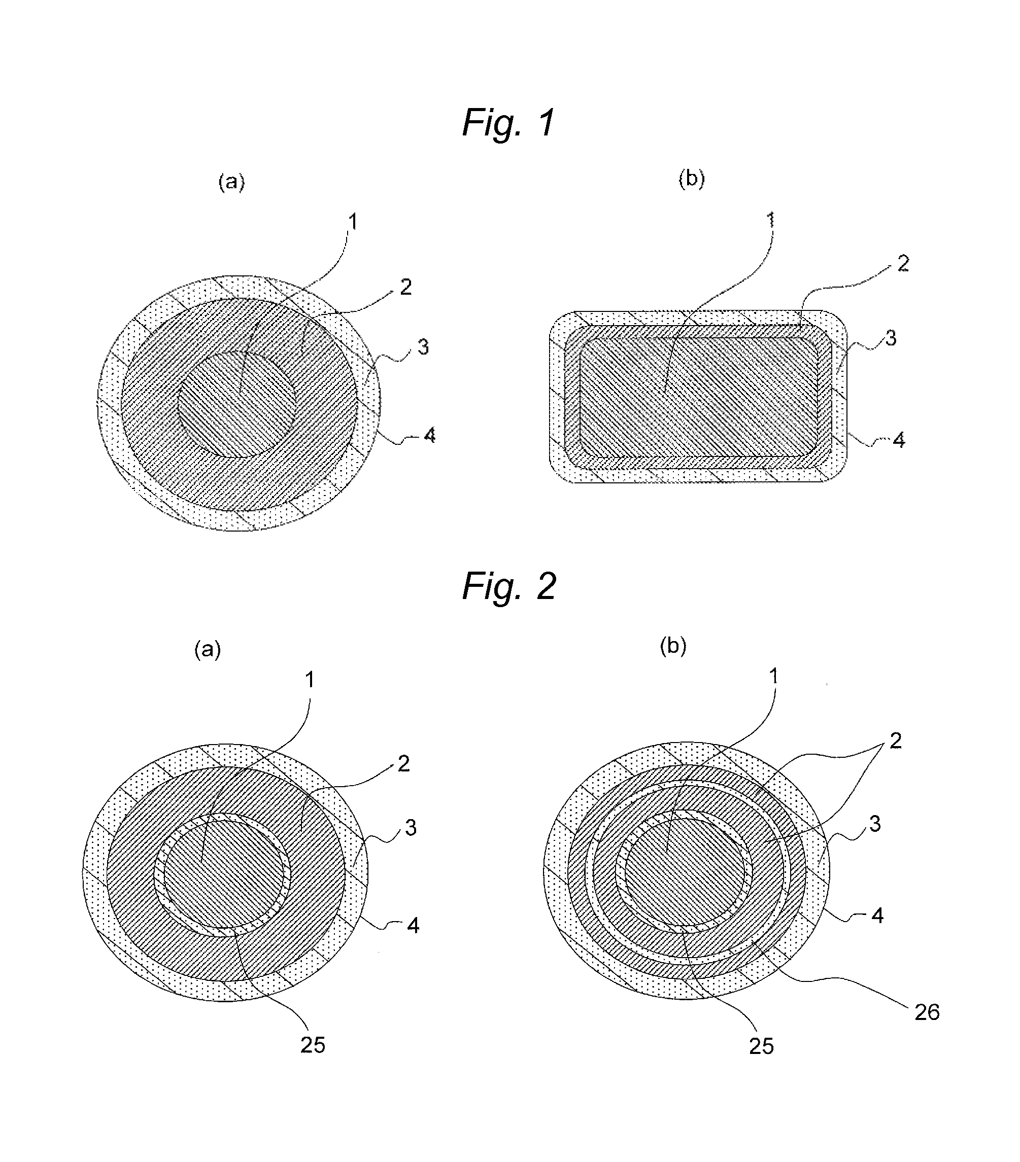
[0063]An insulated wire (see FIG. 2(a)) composed of a foamed polyamideimide layer (thickness: 18 μm), an inner filled layer (4 μm) of polyamideimide, and an outer filled layer (4 μm) containing silica (grain size: 15 nm) at a proportion of 20% in polyamideimide was obtained. The bubble size was 4 μm.

example 2

[0064]An insulated wire (see FIG. 2(a)) composed of a foamed polyamideimide layer (thickness: 18 μm), an inner filled layer (4 μm) of polyamideimide, and an outer filled layer (5 μm) containing titanium dioxide (grain size: 15 nm) at a proportion of 20% in polyamideimide was obtained. The bubble size was 4 μm.

example 3

[0065]An insulated wire (see FIG. 2(a)) composed of a foamed polyamideimide layer (thickness: 18 μm), an inner filled layer (4 μm) of polyamideimide, and an outer filled layer (4 μm) containing titanium dioxide (grain size: 15 nm) at a proportion of 30% in polyamideimide was obtained. The bubble size was 4 μm.


PUM

PropertyMeasurementUnit
relative dielectric constantaaaaaaaaaa
bubble sizeaaaaaaaaaa
relative dielectric constantaaaaaaaaaa

Abstract

An insulated wire, containing: a conductor; a foamed insulating layer; and an unfoamed filled layer on the outer circumference of the foamed insulating layer, in which the filled layer contains a partial discharge resistant material, which insulated wire has all of high partial discharge inception voltage, resistance to partial discharge, heat resistance, and abrasion resistance (scratch resistance).

Description

CROSS-REFERENCE TO RELATED APPLICATIONS[0001]This application is a continuation of PCT / JP2013 / 056170 filed on Mar. 6, 2013 which claims benefit of Japanese Patent Application No. 2012-051037 filed on Mar. 7, 2012, the subject matters of which are incorporated herein by reference in their entirety.TECHNICAL FIELD[0002]The present invention relates to an insulated wire, an electrical equipment, and a method of producing an insulated wire.BACKGROUND ART[0003]Inverters have been employed in many types of electrical equipments, as an efficient variable-speed control unit. Inverters are switched at a frequency of several kHz to tens of kHz, to cause a surge voltage at every pulse thereof. Inverter surge is a phenomenon in which reflection occurs at a breakpoint of impedance, for example, at a starting end, a termination end, or the like of a connected wire in the propagation system, followed by applying a voltage twice as high as the inverter output voltage at the maximum. In particular, ...

Claims


Application Information

Patent Timeline
Patent Type & Authority Patents(United States)
IPC IPC(8): H01B13/06C09D179/08C08L79/08H01B7/02H01B3/30H01B7/29H01F5/06
CPCH01B7/0216C08L79/08C09D179/08H01B3/306H01B13/065C08K3/36H01B3/308H01B7/0233H01B7/292H01F5/06C08K2003/2241C08K3/22
Inventor MUTO, DAISUKEOYA, MAKOTONAKA, SATOSHI
Owner ESSEX FURUKAWA MAGNET WIRE LLC
Learn More