
Phase shift circuit and antenna device comprised of at least one movable dielectric body overlapping with an intersecting part of a conductor

a phase shift circuit and dielectric body technology, applied in waveguide devices, basic electric elements, electrical equipment, etc., can solve the problem and achieve the effect of increasing the width-direction size of the base-station antenna

Active Publication Date: 2016-09-06
HITACHI METALS LTD
View PDF9 Cites 0 Cited by
  • Summary
  • Abstract
  • Description
  • Claims
  • Application Information

AI Technical Summary

Benefits of technology

This design reduces the width-direction size of the phase shift circuit and base-station antenna, simplifies the moving mechanism, and maintains impedance matching and phase control, thereby minimizing wind-pressure loads and installation site requirements.

Problems solved by technology

When the width-direction size of the base-station antenna is increased, the following problems arise.

Method used


Image

  • Phase shift circuit and antenna device comprised of at least one movable dielectric body overlapping with an intersecting part of a conductor
  • Phase shift circuit and antenna device comprised of at least one movable dielectric body overlapping with an intersecting part of a conductor
  • Phase shift circuit and antenna device comprised of at least one movable dielectric body overlapping with an intersecting part of a conductor

Examples


embodiment

[0029]An embodiment will be described with reference to FIG. 1 to FIG. 8. In the description of the present embodiment, abase-station antenna and a phase shift circuit applied to the base-station antenna are taken as an example.

[0030]

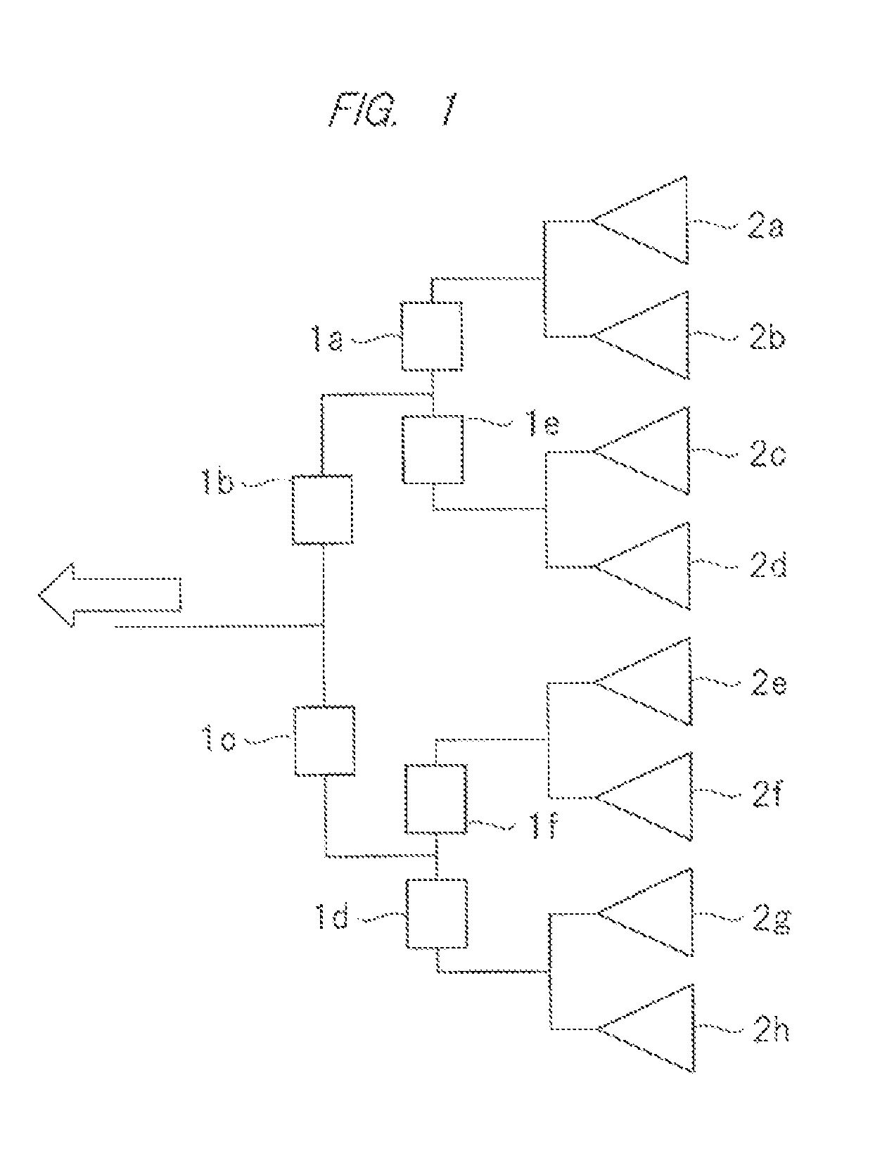
[0031]First, a configuration of the base-station antenna according to the present embodiment will be described with reference to FIG. 1. FIG. 1 is a schematic drawing showing an example of the configuration of the base-station antenna.

[0032]As shown in FIG. 1, the base-station antenna has an input terminal (not shown) to which a high-frequency signal output from a high-frequency circuit (not shown) or the like is input, a plurality of phase shift circuits 1a, 1b, 1c, 1d, 1e and 1f (collectively referred to also as “phase shift circuits 1”), and a plurality of antenna elements 2a, 2b, 2c, 2d, 2e, 2f, 2g and 2h (collectively referred to also as “antenna elements 2”). FIG. 1 shows six phase shift circuits 1 and eight antenna elements 2 as an example, but t...


PUM


Abstract

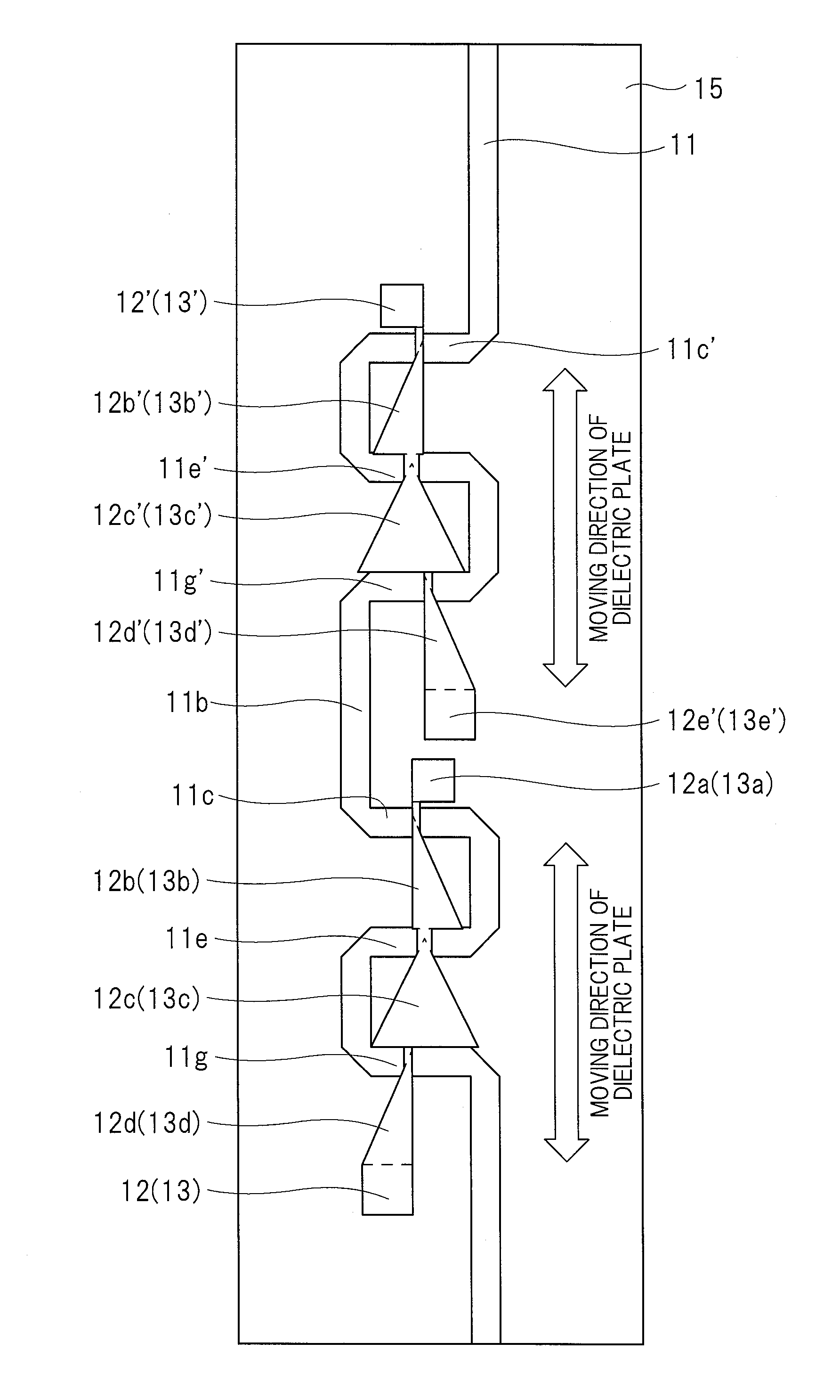
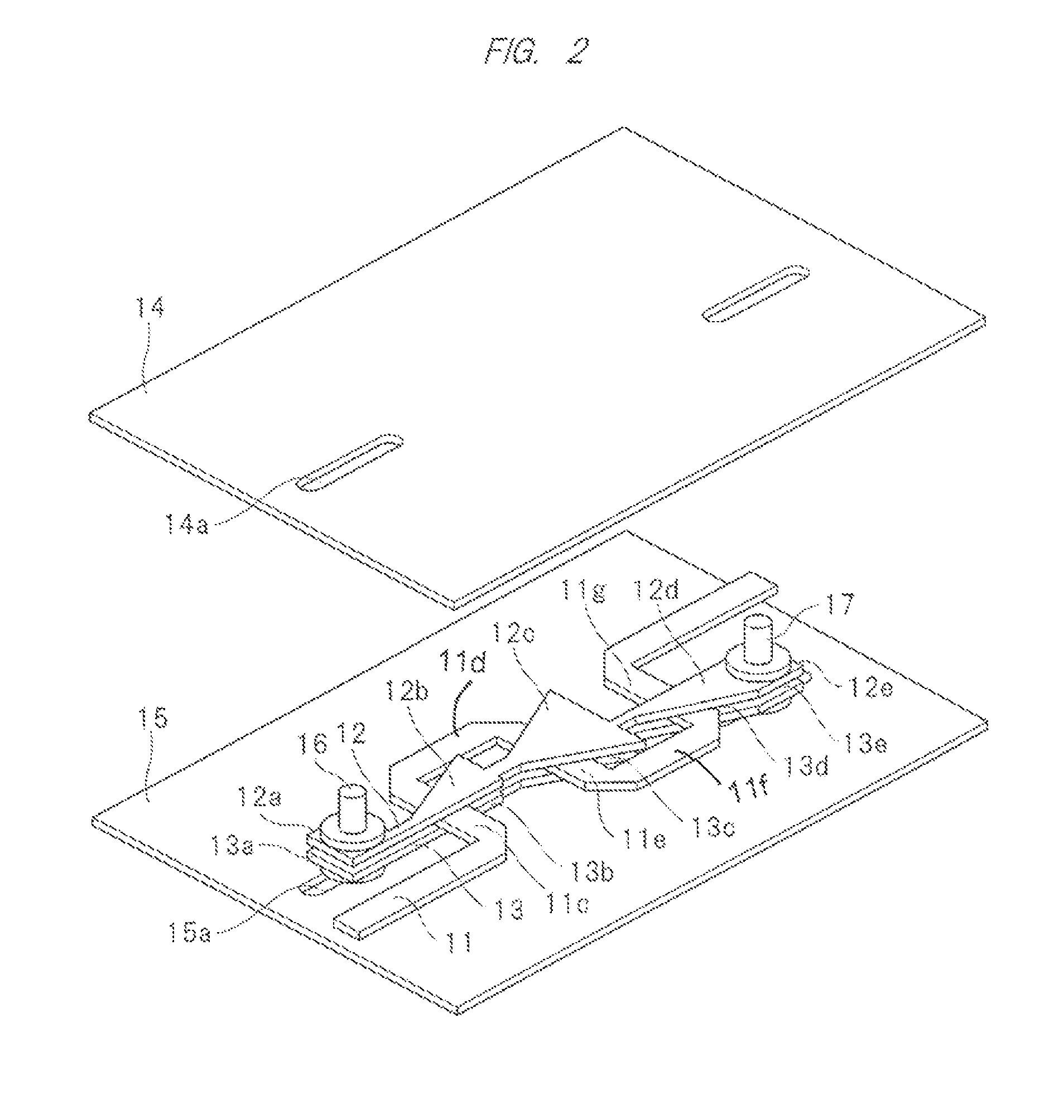
Techniques capable of reducing the width-direction size of a phase shift circuit as much as possible are provided. A phase shift circuit has a signal line, a first dielectric plate, and a second dielectric plate. The signal line has first to third intersecting parts extending in a direction intersecting with a longitudinal direction of the phase shift circuit. On the other hand, the first dielectric plate and the second dielectric plate have first to third overlapping parts overlapping the intersecting parts of the signal line. When the first dielectric plate and the second dielectric plate are moved in the longitudinal direction of the phase shift circuit, the overlapped areas between the intersecting parts of the signal line and the overlapping parts of the first dielectric plate and the second dielectric plate are changed.

Description

CROSS-REFERENCE TO RELATED APPLICATION[0001]The present application claims priority from Japanese Patent Application No. 2013-28406 filed on Feb. 15, 2013, the content of which is hereby incorporated by reference into this application.TECHNICAL FIELD OF THE INVENTION[0002]The present invention relates to a phase shift circuit suitable for an antenna device.BACKGROUND OF THE INVENTION[0003]Conventional phase shift circuits used in a base-station antenna are described in Japanese Patent No. 4745213 (Patent Document 1) and U.S. Pat. No. 5,940,030 (Patent Document 2).[0004]A phase shift circuit described in Patent Document 1 includes a signal line, a ground conductor provided to be opposed to the signal line, and a dielectric plate inserted between the signal line and the ground conductor from a direction perpendicular to a longitudinal direction of the signal line. In the phase shift circuit described in Patent Document 1, the overlapped area between the dielectric plate and the signal...

Claims


Application Information

Patent Timeline
Patent Type & Authority Patents(United States)
IPC IPC(8): H01P1/18H01P9/00
CPCH01P1/184H01P9/00H01P9/006
Inventor SAKASAI, KAZUHIROOGAWA, TOMOYUKI
Owner HITACHI METALS LTD
Learn More