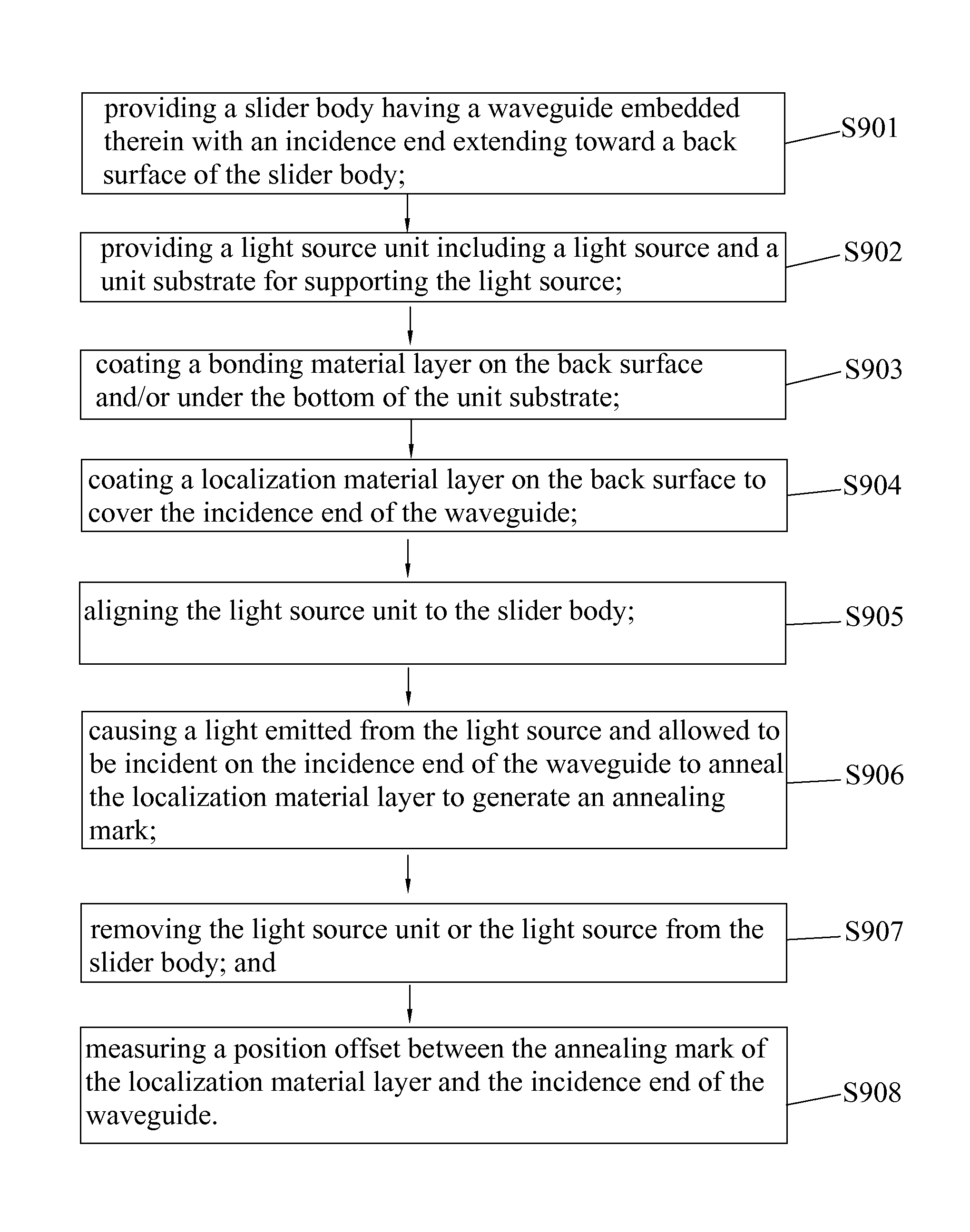
Method of testing thermally-assisted magnetic head
a technology of magnetic head and thermally assisted head, which is applied in the field of hard disk drives, can solve the problems of increasing the anisotropic magnetic field (high coercivity) of the inability of the magnetic head to write data to the magnetic recording medium, and the drop of magnetic fine particles in the thermal stability of magnetization
- Summary
- Abstract
- Description
- Claims
- Application Information
AI Technical Summary
Benefits of technology
Problems solved by technology
Method used
Image

Examples
Embodiment Construction
[0044]Various preferred embodiments of the invention will now be described with reference to the figures, wherein like reference numerals designate similar parts throughout the various views. As indicated above, the present invention is directed to a method of testing a thermally-assisted magnetic head (TAMH), thereby alignment accuracy of a slider body and a light source unit in two dimensional directions can be evaluated.
[0045]FIG. 5 is a perspective view of a disk drive unit of the present invention. As shown, a disk drive unit 1 contains a number of rotatable magnetic disks 12 attached to a spindle motor 13, and a head stack assembly (HSA) 14 which is rotatable about an actuator arm axis 16 for accessing data tracks on the magnetic disks 12 during seeking. The magnetic disk 12 is a type of magnetic recording medium. The HSA 14 contains a set of drive arms 142 and HGAs 100 mounted on the ends of the drive arms 142. Typically, a spindling voice-coil motor (VCM) 18 is provided for ...
PUM
| Property | Measurement | Unit |
|---|---|---|
| thickness | aaaaa | aaaaa |
| current | aaaaa | aaaaa |
| recording density | aaaaa | aaaaa |
Abstract
Description
Claims
Application Information
 - R&D
- Intellectual Property
- Life Sciences
- Materials
- Tech Scout
- Unparalleled Data Quality
- Higher Quality Content
- 60% Fewer Hallucinations
Browse by: Latest US Patents, China's latest patents, Technical Efficacy Thesaurus, Application Domain, Technology Topic, Popular Technical Reports.
© 2025 PatSnap. All rights reserved.Legal|Privacy policy|Modern Slavery Act Transparency Statement|Sitemap|About US| Contact US: help@patsnap.com