
Increasing disaster resiliency by having a pod backed up to other peer pods in a site or beyond

a pod and disaster resiliency technology, applied in the field of computers and computer applications, can solve the problems of inability to restore vms from backups, inability to restore vms, etc., and achieve the effect of increasing disaster resiliency in computers, low probability, and high probability

Inactive Publication Date: 2016-09-06
INT BUSINESS MASCH CORP
View PDF8 Cites 2 Cited by
  • Summary
  • Abstract
  • Description
  • Claims
  • Application Information

AI Technical Summary

Benefits of technology

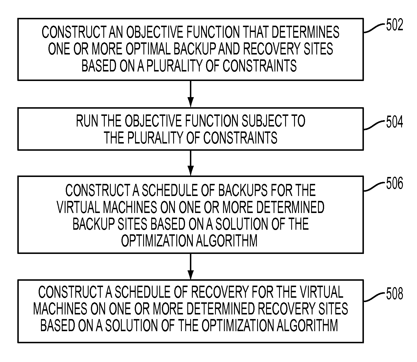
[0004]A method of increasing disaster resiliency in computer systems, in one aspect, may comprise executing an optimization algorithm that solves simultaneously for at least a first objective to increase a spread of a backup of virtual machines from a given site onto other sites in proportion to an amount of available space for backup at each site, a second objective to increase a number of backups at one or more of the other sites with low probability of system crash while reducing backups at one or more of the other sites with higher probability of system crash, and a third objective to minimize a violation of recovery time objectives of the virtual machines during recovery. The method may also comprise determining one or more backup sites and one or more recovery sites in an event the given site crashes based on a solution of the optimization algorithm.

Problems solved by technology

If a disaster strikes the PoD, the VMs may not be able to be restored from the backups since those backups would be lost with the PoD that stores them.
If the cloud PoD (including storage) faces disaster then the VMs cannot be restored.
While the existing literature may point to usage of cloud for disaster recovery (DR), they do not address how the various workloads which are on a cloud can be backed up for disaster recovery in a way so that it is resilient and the recovery exposure is minimized.

Method used


Image

  • Increasing disaster resiliency by having a pod backed up to other peer pods in a site or beyond
  • Increasing disaster resiliency by having a pod backed up to other peer pods in a site or beyond
  • Increasing disaster resiliency by having a pod backed up to other peer pods in a site or beyond

Examples


Embodiment Construction

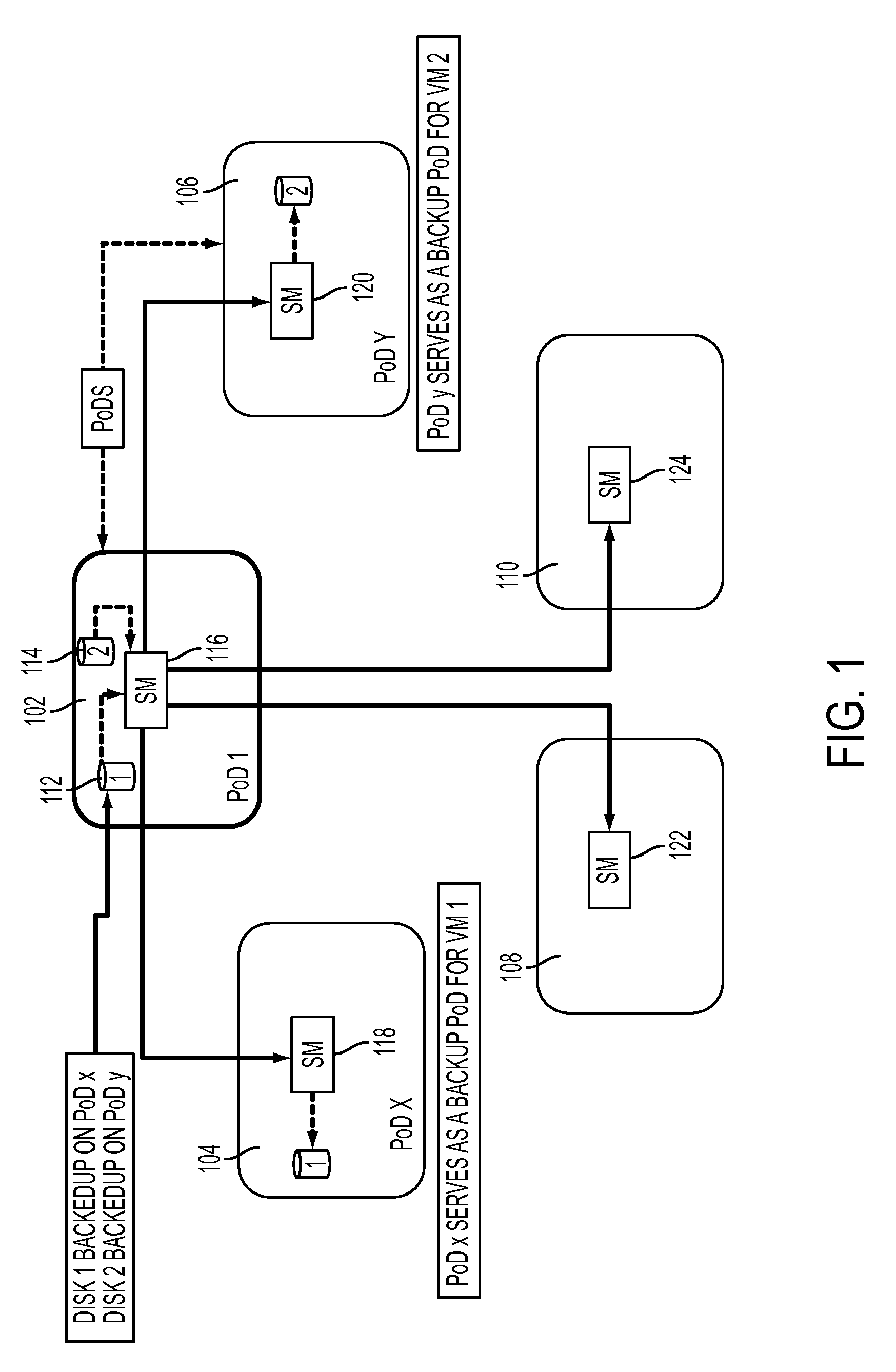
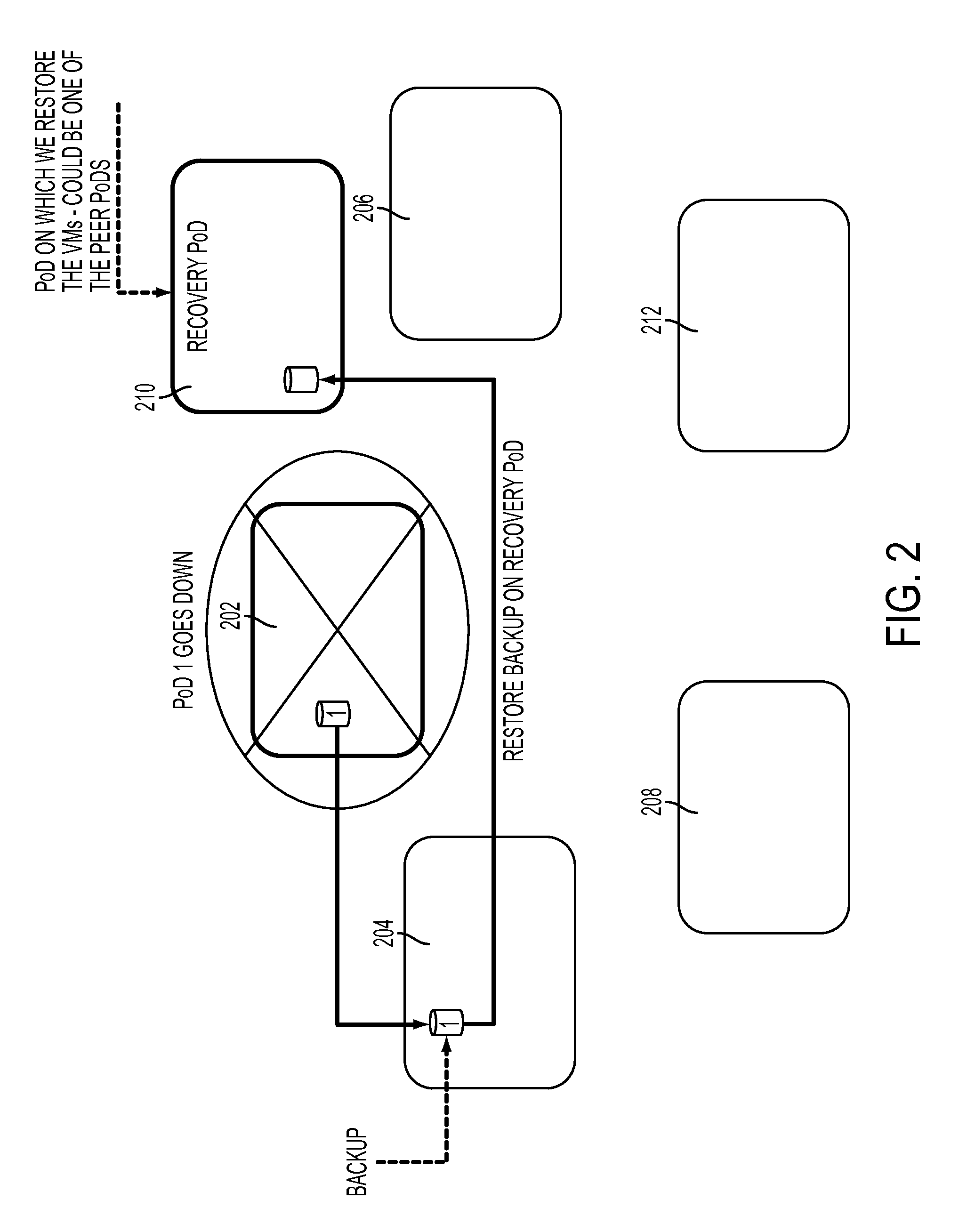
[0014]In one embodiment of the present disclosure, a method and a system may be provided that back up the VMs of a given PoD onto other PoDs or clouds, such that, optimal distribution of backups of a PoD across multiple other PoDs may be achieved, e.g., subject to a set of constraints such as subject to storage capacity, compute capacity, regulatory, and hazard (probability of failure) constraints.

[0015]In one embodiment of the present disclosure, the placement of backups also considers the Recovery Time Objectives (RTOs) of the individual VMs along with the network bandwidth between the PoD on which the backup lies and the Recovery PoD. Briefly, an RTO is the time that it could take to get a system back up and running after a failure.

[0016]In another aspect, a method and a system of the present disclosure consider optimally constructing the schedule of VMs backup on other PoDs to maximize resiliency from disasters affecting more than one PoD.

[0017]Yet in another aspect, a method an...


PUM


Abstract

Increasing disaster resiliency in one aspect may comprise running an optimization algorithm that simultaneously solves for at least a first objective to increase a spread of a backup of virtual machines from a given site onto other sites in proportion to an amount of available space for backup at each site, a second objective to increase a number of backups at one or more of the other sites with low probability of system crash while reducing backups at one or more of the other sites with higher probability of system crash, and a third objective to minimize a violation of recovery time objectives of the virtual machines during recovery. One or more backup sites and one or more recovery sites in an event the given site crashes may be determined based on a solution of the optimization algorithm.

Description

FIELD[0001]The present application relates generally to computers, and computer applications, and more particularly to increasing disaster resiliency of computer systems.BACKGROUND[0002]Backup of virtual machines (VMs) is maintained by a storage management system within a point of delivery (PoD). If a disaster strikes the PoD, the VMs may not be able to be restored from the backups since those backups would be lost with the PoD that stores them. For example, in a cloud-based infrastructure, backup of existing VMs running in a cloud is typically achieved by using the storage subsystem within the cloud PoD, which hosts the VMs. If the cloud PoD (including storage) faces disaster then the VMs cannot be restored.[0003]Current approaches to disaster management include periodic tape backups that are trucked offsite to continuous (a) synchronous replication of data between geographically separated sites. While the existing literature may point to usage of cloud for disaster recovery (DR), ...

Claims


Application Information

Patent Timeline
Patent Type & Authority Patents(United States)
IPC IPC(8): G06F11/14
CPCG06F11/1469G06F11/1461G06F11/1451G06F11/1456G06F11/1464G06F2201/815G06F11/1458G06F2201/805
Inventor GUPTA, MANISHHARPER, RICHARD E.
Owner INT BUSINESS MASCH CORP
Learn More