
Gravity compensation device and lift apparatus including the same

a compensation device and gravity technology, applied in the direction of mine lifts, hoisting equipment, elevators, etc., can solve the problems of increasing air consumption, requiring troublesome work, and difficult to so as to reduce the influence of force variation and easily deal with load weight variation

Active Publication Date: 2016-08-30
PANASONIC INTELLECTUAL PROPERTY MANAGEMENT CO LTD
View PDF22 Cites 0 Cited by
  • Summary
  • Abstract
  • Description
  • Claims
  • Application Information

AI Technical Summary

Benefits of technology

The present invention provides a gravity compensation device and a lift apparatus with the gravity compensation device that can easily handle changes in load weight without using gas. The force generated by the gas actuator is transmitted to the lift section through a link that is axially shiftable, reducing the impact of force variations caused by the gas actuator displacement. This allows for easy adjustment of the load weight, and there is no gas consumption during the lift section displacement.

Problems solved by technology

However, in the case of adopting the configuration including, as the measure to compensate for gravity, the counter weight, an elastic member such as the constant force spring or a spring, there is required troublesome work such as replacement of a component or modification of the structure in order to deal with variation of load weight applied by an object.
Furthermore, force is applied to the elastic member in a state where load weight is applied, in which case it is more difficult to deal with variation of load weight.
However, in a conventional configuration, air needs to be charged or discharged every time displacement occurs, resulting in an increase in consumption of air, which is problematic.

Method used


Image

  • Gravity compensation device and lift apparatus including the same
  • Gravity compensation device and lift apparatus including the same
  • Gravity compensation device and lift apparatus including the same

Examples


first embodiment

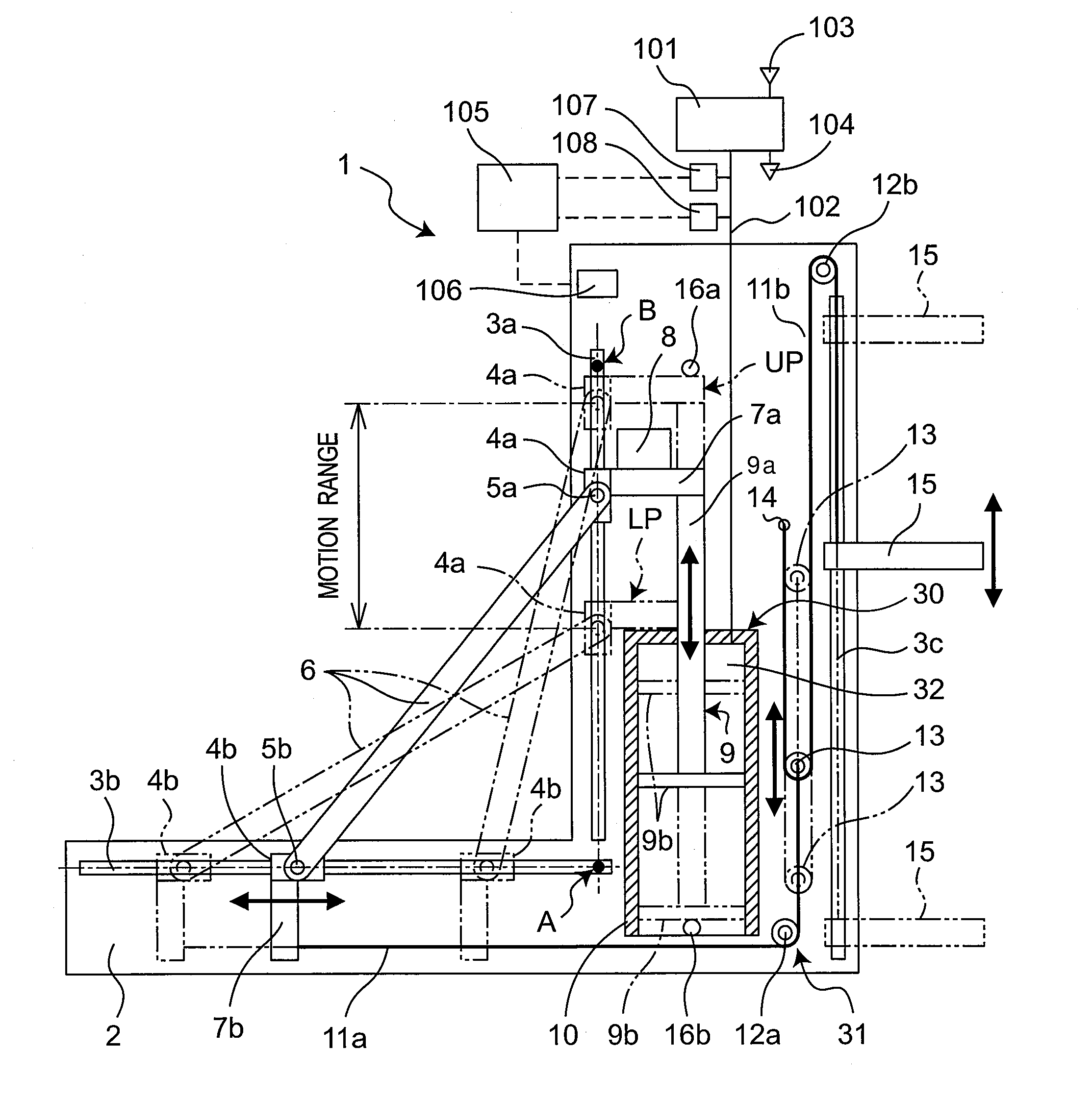
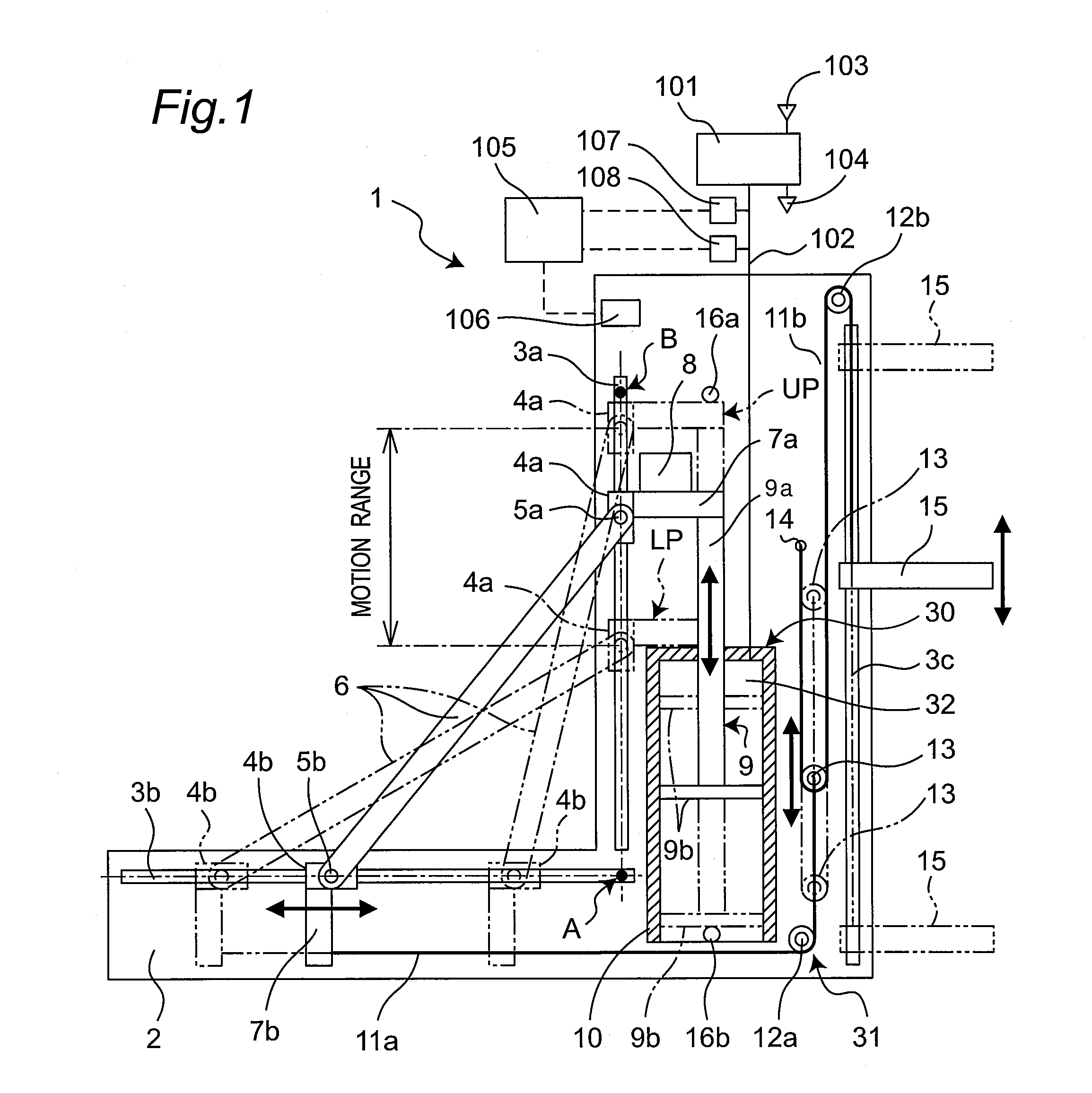
[0046]FIG. 1 schematically shows a gravity compensation device 1 according to the first embodiment of the present invention. The gravity compensation device 1 includes a frame 2, a link 6, a gas actuator 30, a lift section 15, and a coupling section 31, so as to compensate for gravity effects applied onto the lift section 15.

[0047]In FIG. 1, the frame 2 in the gravity compensation device 1 serves as one example of a base and is bent in an L shape. The gravity compensation device also includes first, second, and third guide rails 3a, 3b, and 3c, which are fixed to the frame 2. The first and second guide rails 3a and 3b serve as one example of two shafts that are located on an ordinate axis in the vertical direction and on a transverse axis in the horizontal direction, respectively, and are fixed to the frame 2 and cross each other at a predetermined angle. The ordinate axis and the transverse axis include a first reference point A that is located at the bent portion of the frame 2. F...


PUM


Abstract

A link has first and second ends coupled, so as to be axially shiftable, respectively to two shafts that include a reference point located in a base and cross each other. A gas actuator has an inner space that has gas pressure pressing the first end of the link toward the reference point so as to shift the first end of the link such that a distance between a first end position of the link and the reference point is equal to or more than a distance between the first and second ends in a state where the inner space has a volume equal to zero obtained by extrapolating variation of the inner space volume relative to the first end position. The second end and a lift section that is vertically shiftable with respect to the base are coupled by means of a coupling section.

Description

CROSS-REFERENCE TO RELATED APPLICATIONS[0001]This is a continuation application of International Application No. PCT / JP2012 / 002305, with an international filing date of Apr. 3, 2012, which claims priority of Japanese Patent Application No. 2011-124307 filed on Jun. 2, 2011, the content of which is incorporated herein by reference.TECHNICAL FIELD[0002]The technical field relates to a gravity compensation device that reduces consumption of air with use of a link in an apparatus for compensating for the effects of gravity by means of the pressure of compressed gas. The technical field also relates to a lift apparatus including the gravity compensation device.BACKGROUND ART[0003]There have been devised measures to compensate for gravity (weight of an object) and reduce a load applied upon vertically shifting the object, in addition to basic measures such as a counter weight and a constant force spring (see JP 3794743 B1 and JP 4144021 B1, for example).[0004]However, in the case of adopt...

Claims


Application Information

Patent Timeline
Patent Type & Authority Patents(United States)
IPC IPC(8): B66B17/12B66F7/02B66F19/00B66B9/00
CPCB66B17/12B66F7/02B66F19/00B66B9/00
Inventor ASAI, KATSUHIKO
Owner PANASONIC INTELLECTUAL PROPERTY MANAGEMENT CO LTD
Learn More