Swimming pool filter water return fitting

a technology for filter water and swimming pools, applied in the field of installation of filter water return fittings, can solve the problems of lack of uniformity in size and quality, inability to span the width of poured concrete walls, and inability to meet the needs of poured concrete, so as to facilitate the connection of a face plate

Inactive Publication Date: 2016-08-09
WALL FRANK L
View PDF6 Cites 1 Cited by
  • Summary
  • Abstract
  • Description
  • Claims
  • Application Information

AI Technical Summary

Benefits of technology

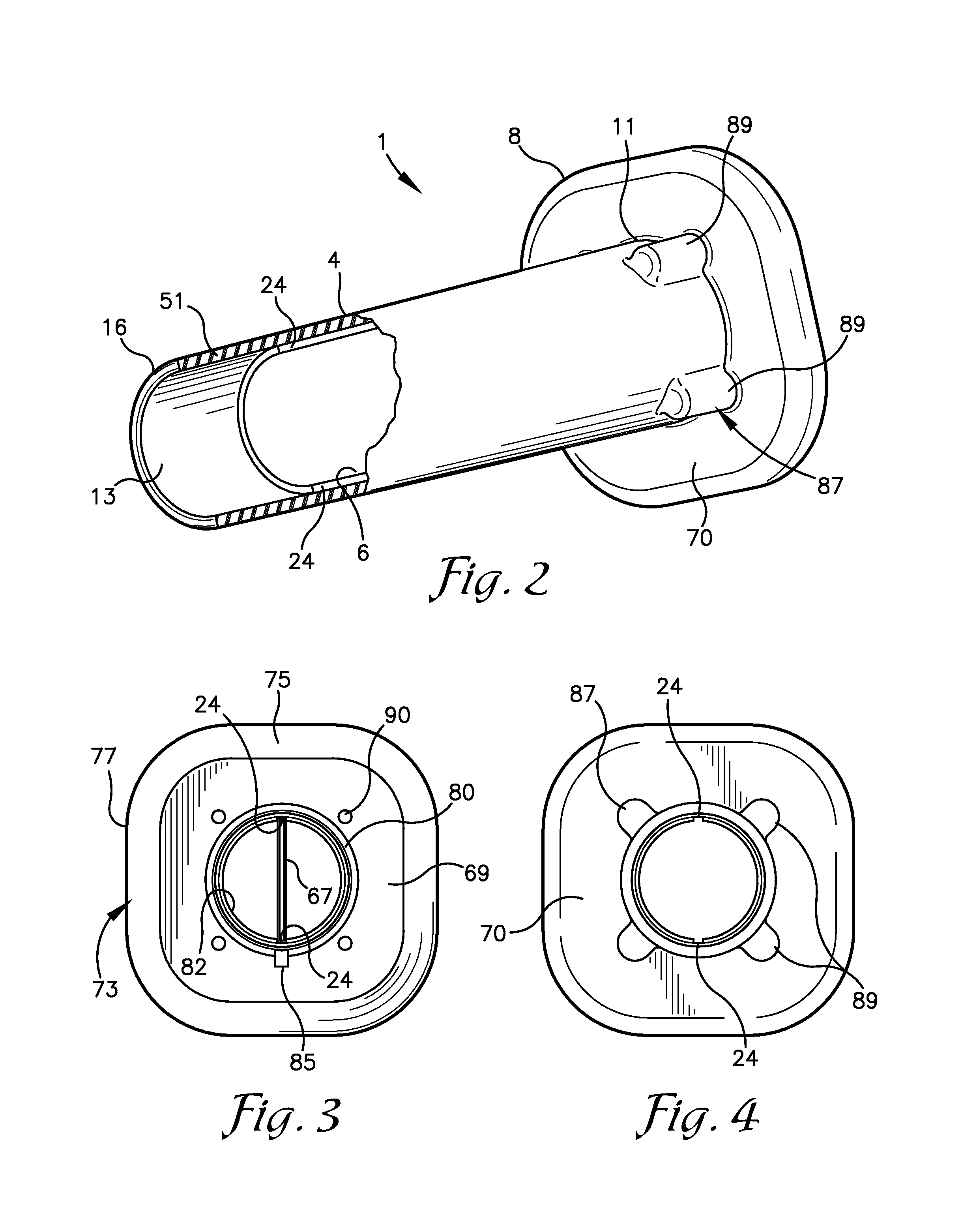
[0013]The present invention is directed to a fitting for a pool wall which is adapted to be secured to and supported on a wall tie used with a wall form assembly for forming a poured wall for the swimming pool. The fitting includes a tubular stem or body with a bore extending therethrough. A wall tie is inserted through the bore of the fitting and into or through one or more grooves associated with the fitting to prevent rotation of the fitting relative to the wall tie with the wall tie supporting the fitting to prevent it from being dislodged vertically or horizontally when concrete is poured in to the wall form assembly and around the fitting. In a preferred embodiment, a pair of grooves are formed in the fitting, projecting radially outward from the bore in planar alignment. Upper and lower edges of the wall tie are then received in the grooves either directly or indirectly through one or more extenders secured on the wall tie.
[0015]A face plate mounting flange may be formed on the tubular stem to facilitate connection of a face plate to the fitting and to form a water tight seal between the fitting and a pool liner extending therearound by compressing the pool liner against an annular gasket positioned between the pool liner and the mounting flange. The tubular stem or body in combination with the mounting flange may be considered the fitting body. The face plate may be of any desired geometry, however, the fitting is particularly well adapted for use with a square mounting flange and a square face plate as mounting of the grooved fitting on a vertically oriented wall tie allows the fitting to be properly oriented with the upper and lower peripheral edges of the mounting flange and the face plate extending horizontally and the sides extending vertically. More specifically, the grooves in the fitting preferably lie in a plane extending parallel to two of the sides of the mounting flange and perpendicular to the remaining sides. A keyway formed on the back of the face plate aligns with a key formed on the mounting flange to orient the sides of the square face plate in parallel alignment with the sides of the mounting flange.

Problems solved by technology

A problem with currently available pool water return fittings is that they are not long enough to span the width of a poured concrete wall.
Because currently available fittings are not long enough to span the width of a poured concrete wall, a makeshift extension must be created and attached to the fitting if such a wall is desired.
These extensions are often made on site with leftover fittings and piping, and because each extension is made on an as-needed basis, they lack uniformity in size and quality.
Typically, the return fitting is screwed to the inner form which leaves the extension unsupported and cantilevered out from the form, making it susceptible to damage from poured concrete.
Pouring concrete on top of the cantilevered extension can cause it to become vertically or horizontally angled and misaligned.
Also, because the return fitting must be screwed to the inner form, mounting holes must be drilled in the form which results in permanent damage to the form.
If the extension ends up being slightly shorter than the distance between the forms, concrete may surround the unsupported end of the extension and incase it inside the wall, or concrete could leak into the extension's interior.
Conversely, if the extension is too long, it can break when squeezed between the forms.
It is undesirable to use custom-made return fitting extensions every time a poured concrete wall is constructed.
Creating extensions adds time and expense to a swimming pool construction project.
The extensions also face potential damage from the concrete pouring process.

Method used


Image

  • Swimming pool filter water return fitting
  • Swimming pool filter water return fitting
  • Swimming pool filter water return fitting

Examples


Embodiment Construction

[0029]As required, detailed embodiments of the present invention are disclosed herein; however, it is to be understood that the disclosed embodiments are merely exemplary of the invention, which may be embodied in various forms. Therefore, specific structural and functional details disclosed herein are not to be interpreted as limiting, but merely as a basis for the claims and as a representative basis for teaching one skilled in the art to variously employ the present invention in virtually any appropriately detailed structure. The drawings constitute a part of this specification and include exemplary embodiments of the present invention and illustrate various objects and features thereof.

[0030]Certain terminology will be used in the following description for convenience in reference only and will not be limiting. For example, the words “upwardly,”“downwardly,”“rightwardly,” and “leftwardly” will refer to the installed position of the item to which the reference is made. The words ...


PUM


Abstract

A fitting for a poured concrete pool wall comprising a tubular stem with one or more grooves extending therethrough for connecting the fitting to a wall tie used with a pool wall form assembly such that the fitting may be secured on the wall tie during pouring of the pool wall. The fitting spans the gap between inner and outer forms. The fitting may include a square face plate mounting flange with upper and lower edges that are oriented horizontally through the coupling of the wall tie in the fitting grooves. A square face plate may be registered with and then secured to the mounting flange such that the upper and lower edges of the face plate also extend horizontally. The fitting forms a conduit through the pool wall for connection to a water return system or to serve as a niche for securing a pool light therein.

Description

CROSS-REFERENCE TO RELATED APPLICATIONS[0001]This application claims the benefit of provisional application Ser. No. 61 / 730,250, filed on Nov. 27, 2012, entitled SWIMMING POOL FILTER WATER RETURN FITTING.BACKGROUND OF THE INVENTION[0002]1. Field of the Invention[0003]This invention relates to fittings installed in swimming pool walls for returning filtered water into the pool. More specifically, it relates to pool water return fittings installed in poured concrete swimming pool walls.[0004]2. Background & Description of the Related Art[0005]In-ground swimming pools can be built using a variety methods and materials. Pool walls can be made from fiberglass-reinforced plastic, vinyl-lined metal or wood frames, spray-applied gunite, poured concrete and concrete lined with a polymeric sheet material. The present invention is intended for use in swimming pool walls created by pouring a wet concrete mixture into a mold consisting of interlocking wall forms held in place with wall ties incl...

Claims


Application Information

Patent Timeline
Patent Type & Authority Patents(United States)
IPC IPC(8): E04H4/00E04H4/12
CPCE04H4/12
Inventor WALL, FRANK L.
Owner WALL FRANK L
Why Eureka
Try Eureka