
Medical balloon with particles therein

a technology of balloons and particles, applied in the field of medical balloons and to balloon catheters, can solve the problems of reducing reducing the size of the inflation/deflation lumen, so as to avoid the flattening of roughening features, improve the performance characteristics of the balloon, and improve the effect of pliability

Active Publication Date: 2016-08-09
COOK MEDICAL TECH LLC
View PDF29 Cites 7 Cited by
  • Summary
  • Abstract
  • Description
  • Claims
  • Application Information

AI Technical Summary

Benefits of technology

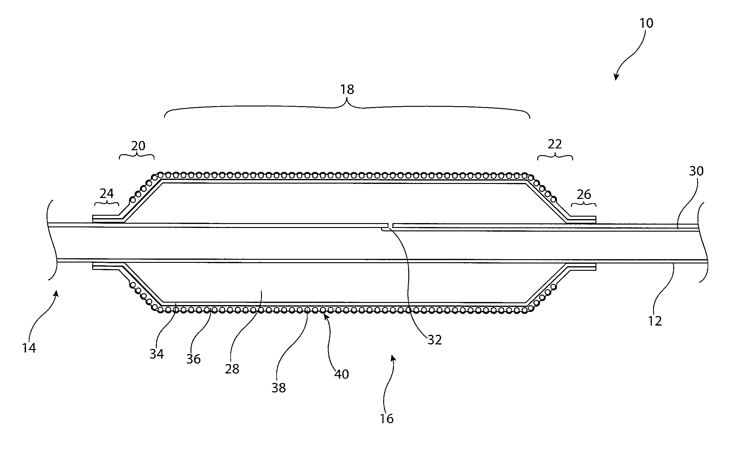
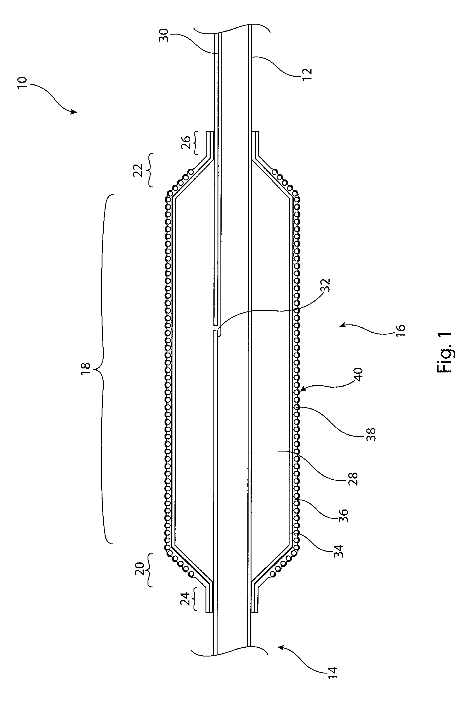
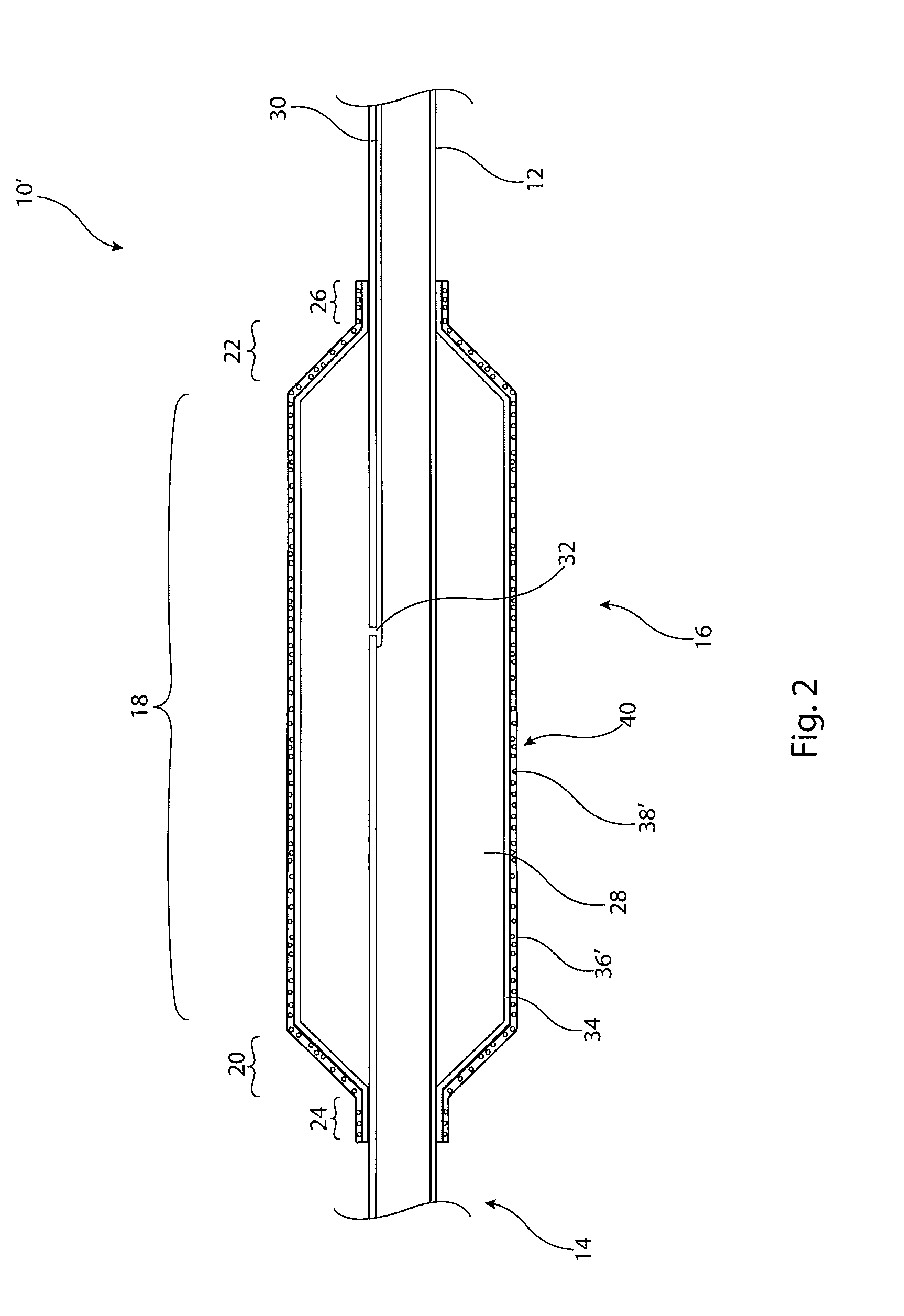
[0009]This structure of balloon includes the advantageous functionality provided by the particles without compromising the performance characteristics of the balloon, in particular its strength and pliability. The provision of an inner layer of polymeric material, which preferably includes no particulate additive, provides strength to the balloon, with the outer layer providing a roughened and / or visible layer. In the case where the particles provide a roughened surface, the inner layer acts as a support which in practice avoids flattening of the roughening features provided by the particles. In the case where the particles provide echogenicity and / or radiopacity, the inner layer similarly provides a support structure to the outer layer, which would otherwise be weaker than a layer which does not have particulate additive. This structure of support layer and outer functional layer retains balloon strength without requiring a large increase in balloon wall thickness.

Problems solved by technology

As a result of this, medical balloons of this nature tend to be very difficult to see by conventional imaging techniques when they are located within a patient.
However, such materials tend to be relatively viscous compared to traditional inflating fluids, such as saline solution, resulting in greater inflating and deflation times of the balloon and also restricting the size of the inflation / deflation lumen which can be used for that balloon.
Moreover, these radiopaque fluids tend not to be particularly biocompatible, leading to potential difficulties should the balloon burst and release fluid into the patient's blood system.
The result of this is that they tend to be relatively slippery.
A slippery balloon can be difficult to position accurately and to hold in position within a patient's vasculature, particularly given the fluid pressure within a patient's vessel.
Migration of the balloon can lead to medical complications.
However, these attempts have not always been successful as surface features tend to flatten as the balloon is stretched during its inflation.

Method used


Image

  • Medical balloon with particles therein
  • Medical balloon with particles therein
  • Medical balloon with particles therein

Examples


Embodiment Construction

[0029]It is to be understood that the drawings are schematic only and are not to scale. They are of a form which is intended to facilitate the understanding of the teachings herein. As a result, similar features, such as layers of the balloon, are not necessarily of the thicknesses or relative thicknesses as appear in the drawings but may be different. For instance, the outer layer of the balloons shown in the drawings and described below in practice is likely to be much thinner than depicted and in particular thinner than the underlying layer of polymeric material.

[0030]In the embodiments shown in the drawings and described below, the medical balloon is shown as being made of two layers, an inner layer and an outer layer. Whilst this is the preferred arrangement for the medical balloon, the teachings herein are not limited to a balloon having two layers only and could, for instance, be formed of a plurality of layers and also to include additional features, such as strengthening el...


PUM

PropertyMeasurementUnit
diameteraaaaaaaaaa
diameteraaaaaaaaaa
diameteraaaaaaaaaa

Abstract

A balloon catheter includes a balloon having a plurality of layers. The inner layer acts as a support layer to the outer layer. Embedded within the outer layer is a plurality of particles or pellets which in one embodiment provide roughening of the outer surface of the balloon. The particles or pellets, particularly in conjunction with an inner support layer, ensure maintenance of the roughened outer surface of the balloon during inflation of the balloon. In another embodiment, the particles or pellets may be radiopaque and / or echogenic with or without creating surface roughening of the balloon.

Description

CROSS-REFERENCE RELATED APPLICATIONS[0001]This application claims priority to GB application no. 1205367.4, filed Mar. 27, 2012, titled “Medical Balloon with Particles Therein,” the contents of which are incorporated herein by reference.TECHNICAL FIELD[0002]The present invention relates to medical balloons and to balloon catheters.BACKGROUND ART[0003]The use of medical balloons and balloon catheters is gaining widespread use in the medical field for effecting a variety of medical procedures, such as angioplasty, vascular dilatation, valvuloplasty, vascular occlusion, deployment and retrieval of implantable medical devices and for other clinical applications. There are a number of technical and clinical considerations involved with the design and use of medical balloons including, for example, visibility of the balloon during the medical procedure and also maintaining the position of the balloon in the patient's vasculature. Such medical balloons are typically made of a thin-walled m...

Claims


Application Information

Patent Timeline
Patent Type & Authority Patents(United States)
IPC IPC(8): A61M29/00A61M25/10A61L29/12A61L29/18
CPCA61M25/10A61M25/1029A61L29/126A61L29/18A61M2025/1031A61M2025/1075A61M2025/1086A61M25/1027
Inventor AGGERHOLM, STEENKLAUSEN, ANDERS SCHEELLYSGAARD, THOMASSONNICHSEN, ANNE-METTE HOPPETORP, ALLAN
Owner COOK MEDICAL TECH LLC
Learn More