
Light emitting device material and light emitting device

a technology of light emitting device and material, which is applied in the direction of triarylamine dye, organic chemistry, luminescent composition, etc., can solve the problems of achieving both increased efficiency and prolonged life of the device, and achieve excellent electron blocking properties, high luminance efficiency, and sufficient durable life.

Active Publication Date: 2016-07-12
TORAY IND INC
View PDF12 Cites 12 Cited by
  • Summary
  • Abstract
  • Description
  • Claims
  • Application Information

AI Technical Summary

Benefits of technology

[0017]According to the present invention, there can be provided an organic electric field light emitting device having high luminance efficiency, and further having sufficient durable life.EMBODIMENTS OF THE INVENTION
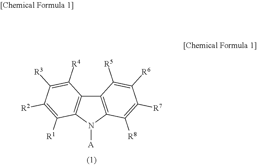
[0018]The compound represented by the general formula (1) in the present invention is described in detail below.
[0020]wherein R1 to R8 may be the same or different and are each selected from the group consisting of hydrogen, an alkyl group, a cycloalkyl group, a heterocyclic group, an alkenyl group, a cycloalkenyl group, an alkynyl group, an alkoxy group, an alkylthio group, an aryl ether group, an aryl thioether group, an aryl group, a heteroaryl group, a halogen, a carbonyl group, a carboxyl group, an oxycarbonyl group, a carbamoyl group, an amino group, a silyl group, —P(═O)R9R10 and a group represented by the following general formula (3); R9 and R10 are each an aryl group or a heteroaryl group, wherein any one of R1 to R8 is a group represented by the following general formula (3), and is coupled at the position of any of R51 to R58 in the general formula (3), or at any position in a group represented by R59, R1 to R8 include none of a dibenzofuran skeleton, a dibenzothiophene skeleton and a carbazole skeleton unless these groups are those represented by the general formula (3), and R1 to R10 include none of an anthracene skeleton and a pyrene skeleton; and A is a group represented by the following general formula (2).
[0022]wherein R11 to R15 may be the same or different and each hydrogen or a substituted or unsubstituted aryl group, wherein at least two of R11 to R15 are substituted or unsubstituted aryl groups, and R11 to R15 include none of an anthracene skeleton and a pyrene skeleton.
[0024]wherein R51 to R59 may be the same or different and are each selected from the group consisting of hydrogen, an alkyl group, a cycloalkyl group, a heterocyclic group, an alkenyl group, a cycloalkenyl group, an alkynyl group, an alkoxy group, an alkylthio group, an aryl ether group, an aryl thioether group, an aryl group, a heteroaryl group, a halogen, a carbonyl group, a carboxyl group, an oxycarbonyl group, a carbamoyl group, an amino group, a silyl group and —P(═O)R60R61; and R60 and R61 are each an aryl group or a heteroaryl group, wherein the position of any one of R51 to R58, or any position in a group represented by R59 is coupled at the position of any of R1 to R8 in the general formula (1), R51 to R59 include none of a dibenzofuran skeleton, a dibenzothiophene skeleton and a carbazole skeleton unless these groups are coupled at the position of any of R1 to R8 in the general formula (1), and R51 to R61 include none of an anthracene skeleton and a pyrene skeleton.
[0025]Among these substituents, hydrogen may be deuterium. The alkyl group denotes a saturated aliphatic hydrocarbon group, such as a methyl group, an ethyl group, a n-propyl group, an isopropyl group, a n-butyl group, a sec-butyl group, or a tert-butyl group, and it may or may not have a substituent. The additional substituent when the alkyl group is substituted is not particularly limited, and examples thereof may include an alkyl group, an aryl group, and a heteroaryl group, and this point is also common to the following descriptions. In addition, the number of carbon atoms in the alkyl group is not particularly limited, but from the viewpoints of easy availability and cost, it is usually within the range of 1 or more and 20 or less, more preferably 1 or more and 8 or less.

Problems solved by technology

However, there are still many technical problems and, especially, attainment of both increased efficiency and prolonged life of a device is one of the major problems.

Method used


Image

  • Light emitting device material and light emitting device
  • Light emitting device material and light emitting device
  • Light emitting device material and light emitting device

Examples


synthesis example 1

Synthesis of Compound [6]

[0117]A mixed solution of 20.9 g of 3-bromocarbazole, 15.0 g of phenylcarbazole-3-boronic acid, 366 mg of palladium acetate, 300 mg of tris(2-methylphenyl)phosphine, 105 ml of a 2M aqueous potassium carbonate solution and 260 ml of dimethoxyethane was refluxed for 6 hours under a nitrogen flow. The solution was cooled to room temperature, and then extracted with 500 ml of toluene. The organic layer was washed with 100 ml of water twice, dried over magnesium sulfate, and then evaporated. The resultant concentrate was purified by silica gel column chromatography and then vacuum-dried to obtain 13.5 g of 9-phenyl-9H,9′H-3,3′-bicarbazole.

[0118]Next, a mixed solution of 20.0 g of 1,3-dibromo-5-chlorobenzene, 19.8 g of phenylboronic acid, 519 mg of bis(triphenylphosphine)palladium(II) dichloride, 217 ml of a 1.5 M aqueous sodium carbonate solution and 370 ml of dimethoxyethane was refluxed for 4 hours under a nitrogen flow. The solution was cooled to room temperat...

synthesis example 2

Synthesis of Compound [156]

[0123]A mixed solution of 20 g of 2-bromonitrobenzene, 17 g of 4-chlorophenylboronic acid, 45 g of tripotassium phosphate, 6.9 g of tetrabutylammonium bromide, 480 mg of palladium acetate and 500 ml of dimethylformamide was heated / stirred at 130° C. for 5 hours under a nitrogen flow. The solution was cooled to room temperature, then poured into 100 ml of water, and extracted with 150 ml of toluene. The organic layer was washed with 100 ml of water three times, dried over magnesium sulfate, and then evaporated. The concentrate was purified by silica gel column chromatography and vacuum-dried to obtain 22 g of 2-(4-chlorophenyl)nitrobenzene.

[0124]Next, a mixed solution of 22 g of 2-(4-chlorophenyl)nitrobenzene, 61 g of triphenylphosphine and 190 ml of o-dichlorobenzene was refluxed for 6 hours under a nitrogen flow. The solution was cooled to room temperature, o-dichlorobenzene was then distilled away under reduced pressure, and the concentrate was purified ...

synthesis example 3

Synthesis of Compound [176]

[0132]A mixed solution of 20.9 g of 3-bromocarbazole, 15.0 g of 9-phenylcarbazole-3-boronic acid, 366 mg of palladium acetate, 300 mg of tris(2-methylphenyl)phosphine, 105 ml of a 2M aqueous potassium carbonate solution and 260 ml of dimethoxyethane was refluxed for 6 hours under a nitrogen flow. The solution was cooled to room temperature, and then extracted with 500 ml of tetrahydrofuran. The organic layer was washed with 100 ml of a saturated saline solution twice, dried over magnesium sulfate, and then evaporated. The resultant concentrate was purified by o-xylene recrystallization and then vacuum-dried to obtain 13.5 g of 9-phenyl-9H,9′H-3,3′-bicarbazole.

[0133]Next, a mixed solution of 10.0 g of 1,3-dibromo-5-chlorobenzene, 9.9 g of phenyl-d5-boronic acid, 130 mg of bis(triphenylphosphine)palladium(II) dichloride, 78 ml of a 2.0 M aqueous sodium carbonate solution and 185 ml of dimethoxyethane was refluxed for 4 hours under a nitrogen flow. The soluti...


PUM

PropertyMeasurementUnit
resistanceaaaaaaaaaa

Abstract

The present invention provides an organic thin-film light emitting device having both high luminance efficiency and durability due to the use of a light emitting device material containing a compound having a specific carbazole skeleton.

Description

TECHNICAL FIELD[0001]The present invention relates to a light emitting device capable of converting electric energy into light, and a light emitting device material to be used for the same. In particular, the present invention relates to a light emitting device capable of being used for areas such as display devices, flat-panel displays, backlight, lighting, interior design, labels, signboards, electrophotography machines, and light signal generators, and also to a light emitting device material to be used for the same.BACKGROUND ART[0002]Researches on an organic thin-film light emitting device in which electrons injected from a cathode and holes injected from an anode emit light when they are recombined in an organic fluorescent body held by both electrodes have been actively conducted in recent years. This light emitting device is characteristic for high luminance light emission in the form of a thin type and under a low driving voltage, and multicolor light emission due to select...

Claims


Application Information

Patent Timeline
Patent Type & Authority Patents(United States)
IPC IPC(8): H01L51/50C09B57/00H05B33/14H01L51/00C09K11/06C07D209/86
CPCH01L51/50C07D209/86C09B57/00C09B57/008C09K11/06H01L51/0072H05B33/14C09K2211/1007C09K2211/1029H01L51/0085H01L51/5016H01L51/5056H10K85/342H10K85/6572H10K50/11H10K2101/10H10K50/15H10K50/17H10K50/00
Inventor NAGAO, KAZUMASATOMINAGA, TSUYOSHIKWON, JINWOO
Owner TORAY IND INC
Learn More