Method for measuring the length of an electric cable that uses an optical fibre element as a sensor

a technology of optical fibre elements and electric cables, applied in the direction of force measurement by measuring optical property variation, using reradiation, instruments, etc., can solve the problems of unpractical cable length measurement, inability to cut and fit cable length sections, and inability to achieve the measurement of cable length by using a mechanical device moving along the cable length. , to achieve the effect of reducing the splicing procedure and achieving higher quality results

Active Publication Date: 2016-06-21
PRYSMIAN SPA
View PDF22 Cites 3 Cited by
  • Summary
  • Abstract
  • Description
  • Claims
  • Application Information

AI Technical Summary

Benefits of technology

The patent describes a way to make cables that have splice connectors in the factory to reduce the work in the field. The cables also have an optical fibre unit that can be used to accurately measure the length of the cable. This allows for the production of cables that are mechanically consistent and reliable. The optical fibre is surrounded by a protective sheath to improve its mechanical resistance.

Problems solved by technology

In this case, if the cable length section between subsequent splice connectors does not correspond to the required length section in the environment of use, the cable section could result to be too short or too long to be connected to the existing splice locations along the cable route.
Especially in case of cable sections containing multiple cable spans it may not be straightforward to cut and fit the cable length sections.
The Applicant has observed that measurement of cable length by using a mechanical device that moves along the cable length may be unpractical when deployment of the cable follows a complex route and / or the cable length is relatively large, e.g. exceeding 1 km.
This fact introduces an uncertainty in the determined cable length.

Method used


Image

  • Method for measuring the length of an electric cable that uses an optical fibre element as a sensor
  • Method for measuring the length of an electric cable that uses an optical fibre element as a sensor
  • Method for measuring the length of an electric cable that uses an optical fibre element as a sensor

Examples


Embodiment Construction

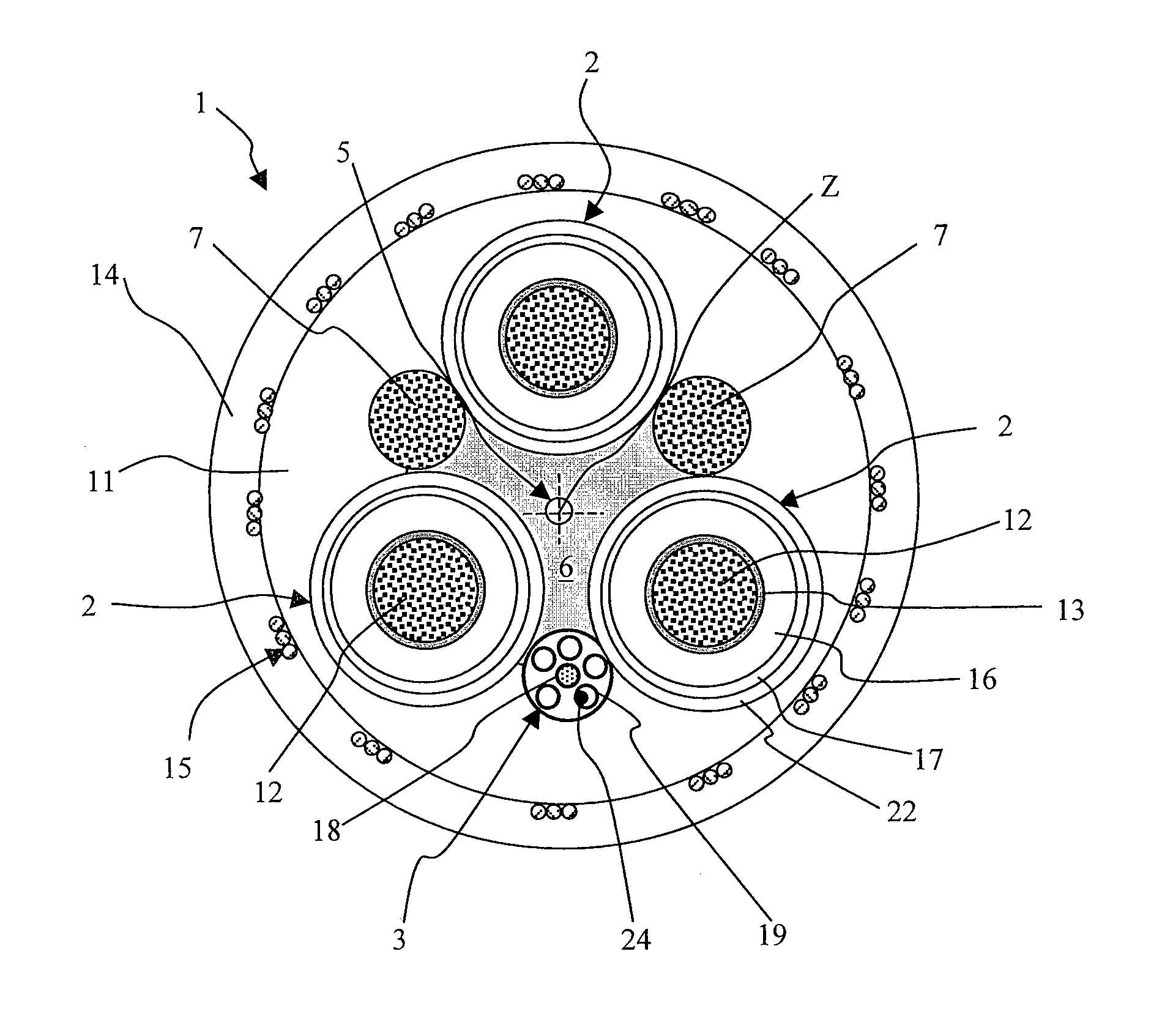
[0043]FIG. 1 illustrates a cross-sectional view of an electric cable, according to an embodiment of the present invention. Cable 1 is a round cable comprising three cores 2 radially arranged about a central longitudinal axis Z of the cable. The cores 2 can provide three-phase power transmission. Cable 1 can be a low or medium voltage power cable, where low voltage indicates a voltage of up to 1 kV and medium voltage indicates a voltage of from 1 kV to 60 kV. Each core 2 comprises an electrical conductor 12, for example a copper conductor formed by a bundle of tinned or bare copper electrical wires stranded together according to conventional methods. In radial external position with respect to each electrical conductor 12, an inner semi-conductive layer 13, an insulating layer 16, and an outer semi-conductive layer 17 are sequentially provided. Inner semi-conductive layer 13, insulating layer 16 and outer semi-conductive layer 17 are made of polymeric-based materials that can be extr...


PUM

PropertyMeasurementUnit
voltageaaaaaaaaaa
lengthsaaaaaaaaaa
lengthaaaaaaaaaa

Abstract

A method of measuring the length of an electric cable, includes providing an electric cable having a cable length and including a cable neutral axis, and a fiber unit longitudinally extending along the cable and including an optical fiber arranged substantially along the neutral axis, wherein the optical fiber is mechanically coupled with the cable; injecting an optical signal into the optical fiber; detecting back-scattered light from the optical fiber responsive to the injected optical signal; analyzing the detected back-scattered light as a function of time so as to determine the length of the optical fiber, and deriving the cable length from the length of the optical fiber.

Description

CROSS REFERENCE TO RELATED APPLICATION[0001]This application is a national phase application based on PCT / IT2010 / 000475, filed Nov. 29, 2010, the content of which is incorporated herein by reference.BACKGROUND OF THE INVENTION[0002]1. Field of the Invention[0003]The present invention is directed to a method for measuring the length of an electric cable.[0004]2. Description of the Related Art[0005]The length of a cable can play a critical role in the transmission of the signals carried thereby. WO 2010 / 126467 discloses a method for indicating the input cable length for serial digital interface signals. The method comprises measuring a differential that varies between first (+1 V) and second values (−1 V) approximately linearly in proportion to a characteristic of a signal at an end of the cable, and translating the measured differential voltage into a cable length measurement.[0006]WO 2010 / 092256 describes a device for measuring the length of a moving cable provided with marks, which...

Claims


Application Information

Patent Timeline
Patent Type & Authority Patents(United States)
IPC IPC(8): G01B11/06G01N3/22G01L1/24G02B6/44G01V3/00G01D5/353G01B11/02G01R31/28H04B10/00
CPCG01B11/02G01D5/35358G01B11/028G02B6/4401
Inventor KNUEPFER, BERNDSARCHI, DAVIDE
Owner PRYSMIAN SPA
Why Eureka
Try Eureka