
Lithium ion battery charging method and battery-equipped device

a technology of lithium ion batteries and charging methods, which is applied in the direction of electrochemical generators, secondary cell servicing/maintenance, transportation and packaging, etc., can solve the problems of reducing the capacity of the battery, serious spoilage of the battery, and reducing so as to reduce the time required for charging and improve the convenience of the battery. , the effect of sacrificing the capacity and the life characteristics of the battery

Active Publication Date: 2016-06-14
PANASONIC INTELLECTUAL PROPERTY MANAGEMENT CO LTD
View PDF18 Cites 14 Cited by
  • Summary
  • Abstract
  • Description
  • Claims
  • Application Information

AI Technical Summary

Benefits of technology

The present invention provides a method for quickly charging lithium ion batteries without damaging their capacity or life. This improves the convenience of battery-equipped devices and reduces the time required for charging. The invention optimizes the charging method by considering various factors such as temperature, voltage, and current. The use of this charging method results in better performance and improved durability of the battery.

Problems solved by technology

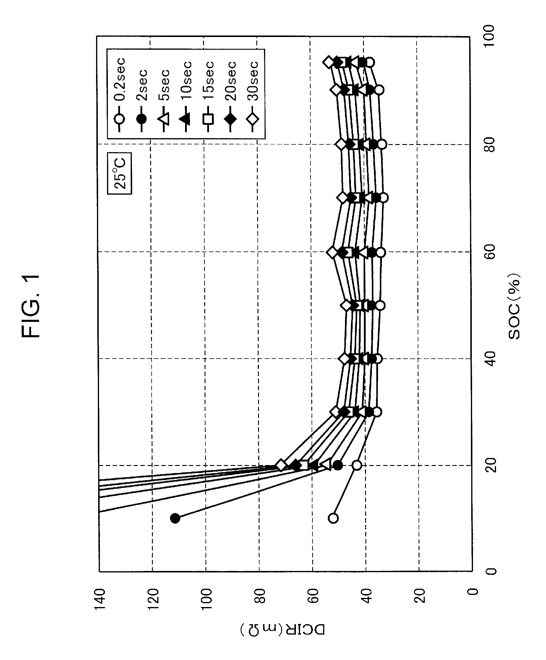
When the lithium ion secondary battery is charged at a voltage not less than a set voltage, battery characteristics are seriously spoiled and deterioration in a capacity and direct current internal resistance (hereinafter referred to as DC-IR) of the battery involved in a charging and discharging cycle is accelerated.
As a result, the capacity of the battery decreases.
That is, when charging is performed at a large charging current, time required for the charging may be reduced and, on the other hand, the battery is damaged and the life characteristics of the secondary battery are spoiled.
It is impossible to use the battery during the charging.
However, it is difficult to realize both a high capacity and quick charge.
As a result, deterioration of the battery is accelerated by the mechanism described above.
However, in the latter half of the charging, since a current value decreases more than necessary, a reduction in a charging time may not be efficiently carried out.
However, in the CV charging, it takes time to reduce the electric current to a target value.
Therefore, damage to the battery progresses.
That is, in the control of the electric current by the CV charging, a sufficient effect may not be obtained for any of the purpose of suppression of damage to the battery and the purpose of reduction in the charging time.

Method used


Image

  • Lithium ion battery charging method and battery-equipped device
  • Lithium ion battery charging method and battery-equipped device
  • Lithium ion battery charging method and battery-equipped device

Examples


working examples

[0087]Next, the present invention is specifically described on the basis of working examples and comparative examples. However, the present invention is not limited to the working examples below.

[0088]A battery 3 shown in FIG. 4 was manufactured as described below. That is, as a positive electrode plate 301, a positive electrode plate obtained by applying a positive electrode mixture to an aluminum foil collector was used. As a negative electrode plate 303, a negative electrode plate obtained by applying a negative electrode mixture to a copper foil collector was used. The thickness of a separator 305 was set to 20 μm. A positive electrode lead collector 302 and the aluminum foil collector were laser-welded. A negative electrode lead collector 304 and the copper foil collector were resistance-welded. The separator 305 was arranged between the positive electrode plate 301 and the negative electrode plate 303 and wound to configure a cylindrical electrode plate group 312. Thereafter, ...


PUM

PropertyMeasurementUnit
pulse timeaaaaaaaaaa
charging voltageaaaaaaaaaa
particle diameteraaaaaaaaaa

Abstract

In a charging method for a lithium ion battery, constant current charging of the lithium ion battery is performed. The constant current charging includes at least three consecutive charging stages. The at least three consecutive charging stages include consecutive first, second, and third charging stages. The second charging stage has a set current value which is set lower than set current values of the first and third charging stages.

Description

RELATED APPLICATIONS[0001]This application is a national phase application of the U.S. National Phase under 35 U.S.C. §371 of International Application No. PCT / JP2012 / 006184, filed on Sep. 27, 2012, which in turn claims the benefit of Japanese Application No. 2011-216341, filed on Sep. 30, 2011, the disclosures of which Applications are incorporated by reference herein.TECHNICAL FIELD[0002]The present invention relates to a lithium ion battery charging method and a battery-equipped device and, more particularly, to a lithium ion battery charging method and a battery-equipped device in which charging is performed in multiple stages.BACKGROUND ART[0003]In recent years, there has been increasing expectation for secondary batteries from an environmental point of view in a global scale. That is, the secondary batteries attract attention as important key items for a reduction in CO2 emissions and are used as power sources for an electric vehicle (EV), a hybrid electric vehicle (HEV), an e...

Claims


Application Information

Patent Timeline
Patent Type & Authority Patents(United States)
IPC IPC(8): H01M10/44H02J7/00H01M10/46H01M10/42H02J7/04
CPCH01M10/44H01M10/46H02J7/0073H02J7/047H01M10/443H01M2010/4271H02J7/044H02J7/00716H02J7/0071Y02E60/10H02J7/04H02J7/007192
Inventor NISHINO, HAJIMETAKENO, MITSUHIROSHIMADA, MIKINARIFUJIKAWA, MASATO
Owner PANASONIC INTELLECTUAL PROPERTY MANAGEMENT CO LTD
Learn More