
Combination compression/diaphragm coupling system

a compression/diaphragm coupling and diaphragm technology, applied in the direction of yielding coupling, rotating vibration suppression, spring/damper, etc., can solve the problems of requiring more operating space than is available, affecting the implementation and performance of couplings, and affecting the performance of couplings

Inactive Publication Date: 2007-12-27
BALDOR ELECTRIC COMPANY
View PDF17 Cites 2 Cited by
  • Summary
  • Abstract
  • Description
  • Claims
  • Application Information

AI Technical Summary

Benefits of technology

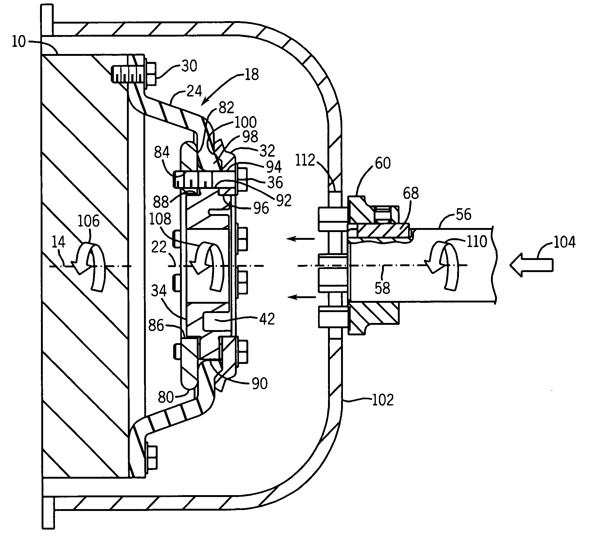
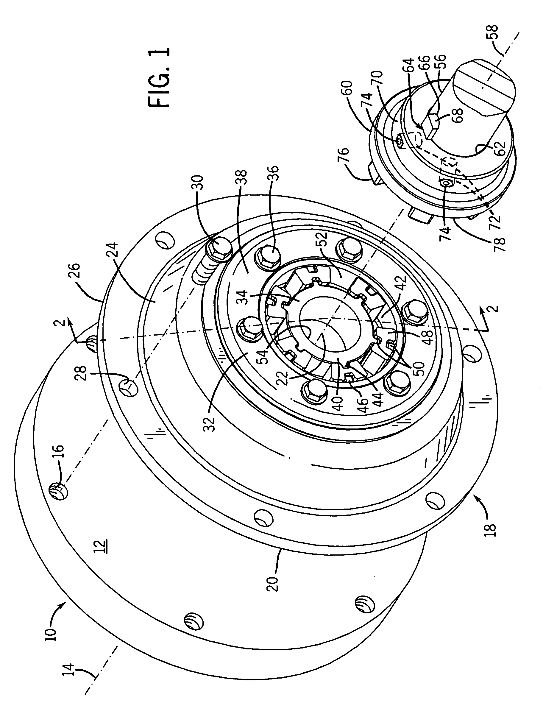
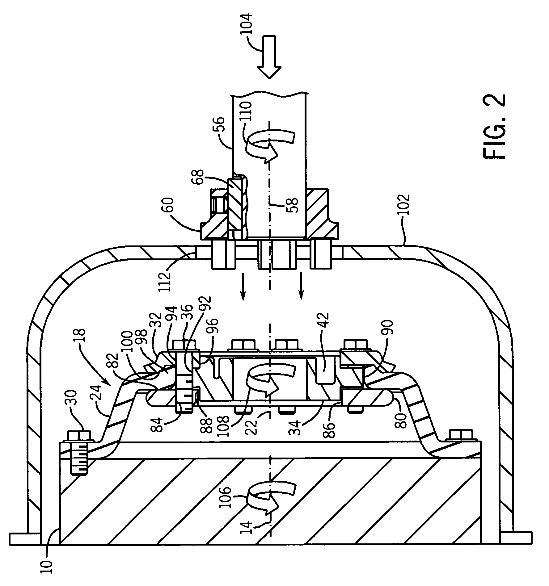
[0008]The present invention offers a solution to all of the issues and problems that currently limit other commercially available mechanical couplings. The invention generally consists of two parts, a flexible hub assembly and a coupling element. The flexible hub assembly is a pre-assembled component that is easily installed and implemented on a first rotating member, thus reducing installation time. The assembly is low profile and can operate in a space-constrained environment. The hub assembly has a flexible element that allows for misalignment between the rotating members as well as functioning as a dampener for vibration isolation. Furthermore, the hub assembly uses elastomeric inserts that allow for reduced internal clearance in the coupling system. The coupling element is adapted to be secured to a second rotating member, and stabbed or axially mated with the hub assembly.
[0009]The net effect is that the system has a higher torque carrying capacity without over constraining the mechanical system or sacrificing coupling life. The system is blindly stabbable and is engaged with very little user interaction. The end user only needs to install the flexible hub assembly and coupling element onto their respective rotating members and then simply slide the two devices together. No further assembly is required eliminating the need to complete the coupling when direct access might be limited. All of these benefits reduce the time and difficulties in coupling one mechanical system to another without sacrificing performance or safety.

Problems solved by technology

All of these couplings have limitations that impact their implementation and performance when used in a mechanical system.
One limitation is that the couplings can be bulky and require more operating space than is available.
Another limitation is that existing coupling systems are often difficult to install and implement, as well as to service, thus leading to a longer installation and downtime.
In a particular application involving engine driven equipment, installation of a flywheel-mounted coupling element, along with mounting of its interfacing components on a driven shaft can be extremely tedious and time-consuming.
This is particularly the case when the application calls for the driven load (such as a pump) is supported on the engine itself, as the coupling elements will be at least partially surrounded by support structures and therefore difficult to access.
A further limitation results from the misalignment of the coupled shafts.
Practically speaking, this misalignment can never be completely eliminated.
Some commercially available couplings address this issue but often do so at the cost of reduced torque carrying capacity.
This can, however, reduce the life of the coupling and its ability to transfer torque efficiently.
Another issue arises as a result of dynamic imbalances inherent in any rotating device.
At high rotations per minute (RPM) these imbalances can result in severe lateral, torsional, and axial vibrations which are then transmitted through the system via the coupling.
These vibrations cause the system to run less efficiently and can also damage vibration sensitive devices, such as bearings.
These covers often complicate the assembly process and make direct access to the coupling system difficult and taxing.
This is particularly problematic when the coupling is only accessible through an access port of very limited dimensions.

Method used


Image

  • Combination compression/diaphragm coupling system
  • Combination compression/diaphragm coupling system
  • Combination compression/diaphragm coupling system

Examples


Embodiment Construction

[0015]Turning now to the drawings, FIG. 1 illustrates a flywheel 10 having a front face 12 and rotating about an axis or centerline 14. The flywheel 10 represents the output interface of the first mechanical device. The flywheel 10 might be attached to an engine, for example, and driven by the engine during operation. The flywheel 10 has a plurality of threaded holes 16 located on the front face 12. The threaded holes 16 are located at a specified distance from the centerline 14 so as to permit securement of the coupling system as described below.

[0016]It should be noted that where, in the present discussion, reference is made to a driving or a driven element, this is for convenience only. As will be appreciated by those skilled in the art, the couplings and systems of the present invention may be used in a variety of contexts and with power or torque flow in the directions indicated here, or in an opposite direction.

[0017]A flexible hub assembly 18 has a mating surface 20 that cont...


PUM


Abstract

A coupling system is disclosed for coupling rotating elements such as a flywheel and a shaft, pairs of shafts, and so forth. A flexible element is captured by a hub. The flexible element may be coupled to a first rotating member, such as a flywheel. The flexible element may be generally disk-like or tire-like. The hub presents an intermeshing interface, such as a series or recesses in a face thereof. A coupling member on the second rotating member has protruding extensions generally parallel to an axis thereof. The extensions intermesh with or engage the recesses of the hub to enable the assembly to be finally installed by stabbing motion of the extensions into the recesses.

Description

BACKGROUND[0001]The current invention relates to the field of mechanical couplings. More specifically, the invention relates to a system that flexibly couples a shaft of one rotating member to a shaft or flywheel of another rotating member.[0002]Mechanical systems often consist of a number of energy converting devices. A few examples of such devices include motors, pumps, alternators, generators, and turbines. These devices are often physically connected to one another via a mechanical coupling to realize the potential of one energy source by converting it into a more useful form. For example, the rotating shaft of an internal combustion engine may drive a flywheel that is, in turn, coupled to the shaft of a pump or other driven device. The mechanical coupling serves to transfer the kinetic energy generated by the engine to drive the load, particularly through transmitting torque to the load during operation.[0003]A variety of mechanical couplings are known and commercially availabl...

Claims


Application Information

Patent Timeline
IPC IPC(8): F16F15/16
CPCF16D1/101Y10T74/2125F16D3/74F16D2003/745
Inventor BURDESHAW, GALEN E.
Owner BALDOR ELECTRIC COMPANY
Learn More