
Noise parameter extraction method

a noise parameter and extraction method technology, applied in the direction of noise figure or signal-to-noise ratio measurement, instruments, resistance/reactance/impedence, etc., can solve the problems of extremely sensitive noise measurement, difficult to handle orders of magnitude, and low level of quantities to be measured

Active Publication Date: 2016-06-14
TSIRONIS CHRISTOS
View PDF9 Cites 3 Cited by
  • Summary
  • Abstract
  • Description
  • Claims
  • Application Information

AI Technical Summary

Benefits of technology

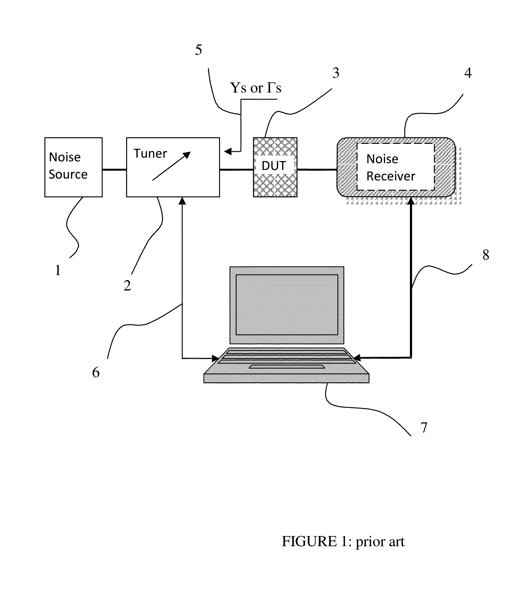
The patent is about a method for measuring and characterizing low noise microwave and RF transistors and amplifiers. The method uses a prior art test setup to measure the noise data and extract the four noise parameters of the DUT. The technical effect of the patent is to provide a more accurate and reliable method for testing and characterizing low noise microwave and RF transistors and amplifiers.

Problems solved by technology

A main difficulty associated with such measurements is the extremely low level of the quantities to be measured: the basic noise available is thermal noise, which amounts to a spectral density of −174 dBm / Hz (or approximately 2*10−18 Watt / Hz) or a receiver with a 1 MHz bandwidth would have to detect reliably a power of 2*10−12 Watt=2 pico-Watt.
It is obvious that these orders of magnitude are difficult to handle and any such power reading will be associated with unavoidable fluctuations.
However, noise measurements are extremely sensitive and various disturbances cause measurement errors and uncertainties.
5 and 6) but is in general cumbersome and prone to insufficiencies, since the DUT may oscillate (see ref.
11) or the impedance tuner may create tuning repeatability and thus measurement errors, which are difficult to identify and eliminate if there are not enough data points to extract from.
This is done in order to increase the measurement speed, at the risk of measurement accuracy.
Tsironis does not disclose a method for using impedance states adapted to the Noise Parameter searched.

Method used


Image

  • Noise parameter extraction method
  • Noise parameter extraction method
  • Noise parameter extraction method

Examples


Embodiment Construction

[0031]FIG. 5 shows the typical dependence of Noise Figure “F” from the source admittance (reflection factor). Equation (1) describes a set of isometric circles on the Smith chart. The center of the smallest circle is the optimum admittance Yopt (or the equivalent Topt) following the relation: Γopt=(Yo−Yopt) / (Yopt+Yo), whereby Yo is the normalization admittance corresponding to the normalization impedance Zo=50Ω(Yo=20 mS). The radius of the isometric noise figure circles increases and their center shifts towards the periphery of the Smith chart as the parameter F increases. A dependence of noise figure across the circles (section Axis A) is shown in FIG. 6. It shows a hyperbolic increase towards the closer edge of the Smith chart (F˜1 / Gs) whereby Gs=Re(Ys) and, approximately, a linear increase towards the far edge of the Smith chart: F˜Rn*Gs.

[0032]In an analytic formulation the relation between noise figure and source admittance is shown in the following equations:

F=Fmin+Rn / Gs*((Gs−G...


PUM


Abstract

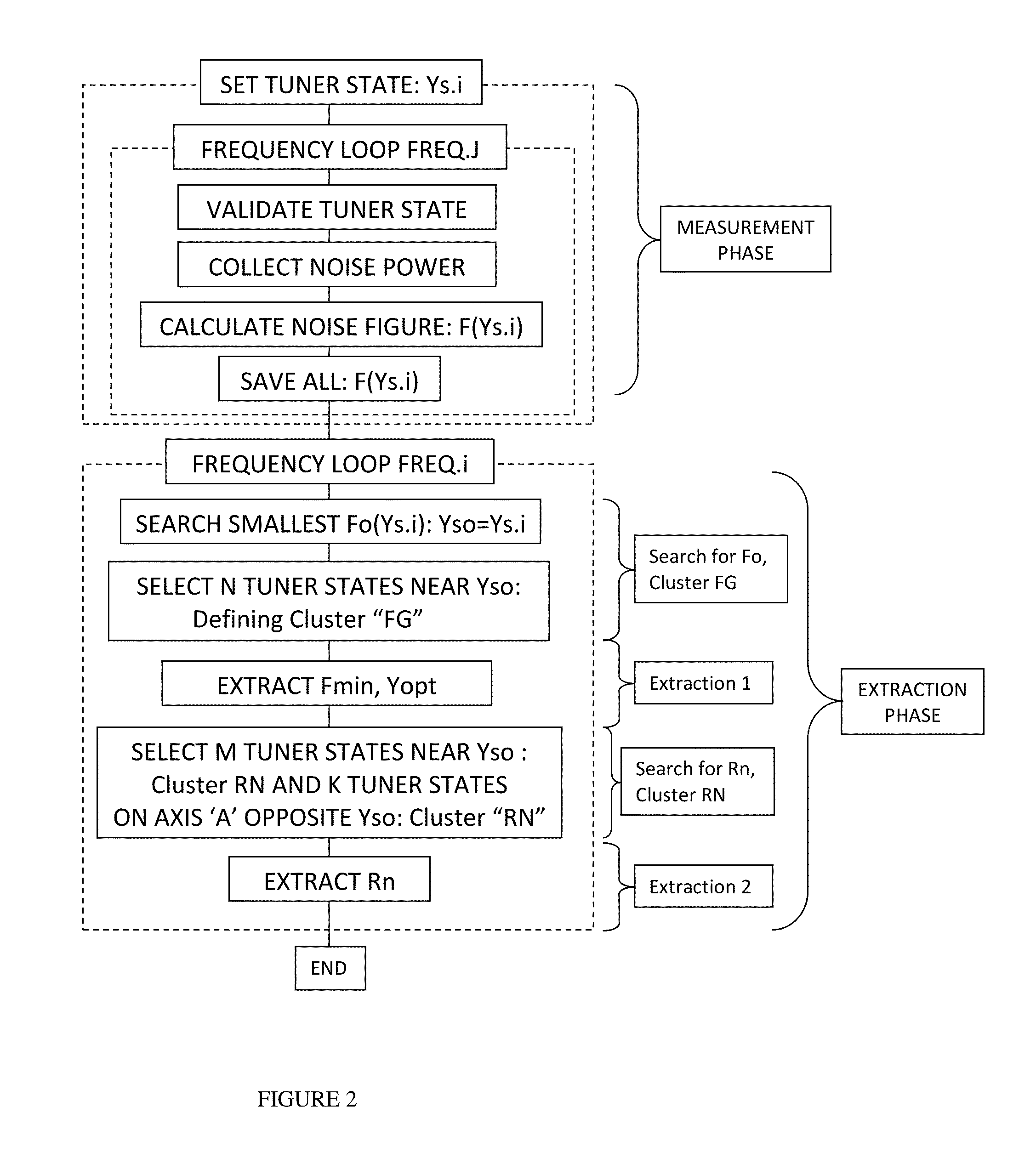
A wideband four noise parameter extraction method uses randomly distributed source states; the data are collected using wideband electro-mechanical tuners and noise and small signal receivers (network analyzers) in fast frequency sweeps; because of the random nature of source impedances reliable noise parameter values are extracted using selected source admittance states, distinctly regrouped in a cluster around the reflection factor associated with the optimum noise figure Fmin and a cluster located anti-diametric to it for determining the equivalent noise resistance Rn. Multiple noise parameter extractions for all possible cross-combinations of source impedance states in each cluster at each measured frequency allows reliable and physically meaningful generation of wideband noise parameters, even for very low noise and potentially unstable DUT's.

Description

PRIORITY CLAIM[0001]Not ApplicableCROSS-REFERENCE TO RELATED ARTICLES[0002]1. H. ROTHE and W. DAHLKE, “Theory of noisy four poles”, Proceedings of the IRE, June 1956, pages 811-818.[0003]2. “Friis formulas for noise”, http: / / en.wikipedia.org / wiki / Friis_formulas_for_noise[0004]3. SISCHKA, Franz, “Basics of S-parameters, part 1”, Characterization handbook, March 2002.[0005]4. TSIRONIS. C. “Noise Parameter Measurement System and Method”, U.S. patent application Ser. No. 13 / 198,966, August 2011.[0006]5. SIMPSON, G. “Data measurement methods and systems”, US Provisional patent application US 2010 / 0030504A1.[0007]6. M. SANNINO, “On the determination of Device Noise and Gain Parameters”, Proceedings IEEE, vol. 67, pages 1364-1382, September 1979.[0008]7. R. LANE, “The determination of Device Noise Parameters”, Proceedings IEEE, vol. 57, pages 1461-1462, August 1969.[0009]8. Patent DE 41 22 189 (1268-P).[0010]9. “Noise Figure Measurement Accuracy—The Y-Factor Method”, Agilent Application No...

Claims


Application Information

Patent Timeline
IPC IPC(8): G01R27/06G01R29/26G01R27/02
CPCG01R27/02G01R29/26G01R31/2616G01R31/2626
Inventor TSIRONIS, CHRISTOS
Owner TSIRONIS CHRISTOS
Learn More