Borehole independent neutron porosity measurement

a neutron porosity and borehole technology, applied in the field of subterranean borehole neutron porosity measurement, can solve the problems of reducing the sensitivity of the far detector (and therefore the far to near count ratio) to formation porosity, adversely affecting the quality of the obtained porosity measurement, and reducing the accuracy of the far detector. the effect of neutron porosity measurement and precise formation porosity measuremen

Active Publication Date: 2016-06-07
SCHLUMBERGER TECH CORP
View PDF22 Cites 0 Cited by
  • Summary
  • Abstract
  • Description
  • Claims
  • Application Information

AI Technical Summary

Benefits of technology

[0012]Exemplary embodiments of the present invention advantageously enable accurate and robust neutron porosity measurements to be made without any compensation and without reliance on the measurement or estimation of sensor standoff and / or borehole caliper. The present invention also enables a more precise formation porosity measurement to be made since all data (e.g., collected while the tool is rotating in the borehole) may be utilized. Those of ordinary skill in the art will readily appreciate that utilizing all collected data advantageously tends to minimizes statistical error. Moreover, neutron porosity measurements made in accordance with the present invention tend to be less affected by borehole rugosity and irregular boreholes where acoustic-based standoff measurements can be problematic.

Problems solved by technology

While the use of dual (near and far) detectors was intended to minimize the effects of the borehole upon the measured formation porosity, it is well known that neutron porosity measurements continue to be adversely affected by changes in the measurement conditions.
Variations from these standard conditions can adversely affect the quality of the obtained porosity measurements.
One drawback with the disclosed method is that such compensation also tends to reduce the sensitivity of the far detector (and therefore the far to near count ratio) to formation porosity.
Reduced sensitivity can in turn lead to an unreliable (or noisy) porosity measurement (due to poor statistics).
As is well known to those of ordinary skill in the art, these drilling fluid parameters are often not well known in-situ.
While this “water compensation” methodology tends to provide improved compensation in low porosity formations, the errors obtained in high porosity formations can be unacceptably large.
Despite the fact that neutron logging techniques have been in commercial use for over 50 years, the interpretation of neutron logs remains challenging and problematic.

Method used


Image

  • Borehole independent neutron porosity measurement
  • Borehole independent neutron porosity measurement
  • Borehole independent neutron porosity measurement

Examples


Embodiment Construction

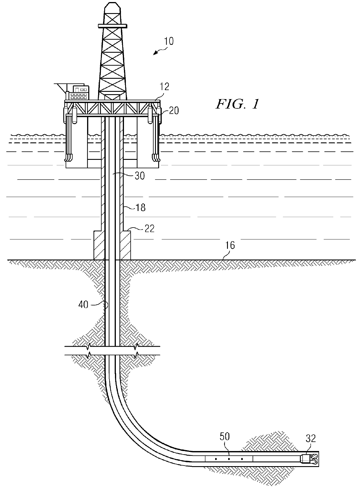
[0029]FIG. 1 depicts one exemplary embodiment of a neutron logging tool 50 in use in an offshore oil or gas drilling assembly, generally denoted 10. In FIG. 2, a semisubmersible drilling platform 12 is positioned over an oil or gas formation disposed below the sea floor 16. A subsea conduit 18 extends from deck 20 of platform 12 to a wellhead installation 22. The platform may include a derrick and a hoisting apparatus for raising and lowering the drill string 30, which, as shown, extends into borehole 40 and includes a drill bit 32 and neutron logging tool 50. Embodiments of neutron logging tool 50 typically include at least one neutron source and first and second axially spaced neutron detectors. Drill string 30 may further include, for example, a downhole drill motor, a mud pulse telemetry system, a steering tool, and / or one or more of numerous other MWD and LWD sensors for sensing downhole characteristics of the borehole and the surrounding formation. The invention is not limited...


PUM

PropertyMeasurementUnit
porosityaaaaaaaaaa
diameteraaaaaaaaaa
diameteraaaaaaaaaa

Abstract

A method for estimating a borehole independent porosity of a subterranean formation includes processing a neutron logging data point, preferably including average near and far detector neutron count rates with suitable input data to obtain the porosity estimate. The borehole independent formation porosity may be obtained without any compensation and without any reliance on the measurement or estimation of sensor standoff and / or borehole caliper.

Description

RELATED APPLICATIONS[0001]None.FIELD OF THE INVENTION[0002]The present invention relates generally to neutron logging of a subterranean borehole. In particular, this invention relates to a method for making neutron porosity logging measurements of a subterranean formation independent of sensor standoff and borehole caliper.BACKGROUND OF THE INVENTION[0003]During hydrocarbon exploration and production, the pore space or “porosity” of a formation is an important property for evaluating the hydrocarbon bearing potential of the formation. Neutron logging measurements are commonly made to obtain a formation porosity estimate. In conventional neutron logging operations, a neutron source emits high energy (“fast”) neutrons into the formation. These fast neutrons are slowed by the surrounding formation (particularly via collisions with hydrogen nuclei present in the formation and the borehole) and eventually captured. The capture of a neutron may result in the emission of one or more prompt...

Claims


Application Information

Patent Timeline
Patent Type & Authority Patents(United States)
IPC IPC(8): G01V5/10G01N15/08E21B47/10
CPCG01V5/10G01N15/08G01V5/107E21B47/1015E21B47/11
Inventor XU, LIBAIHUISZOON, CORNELIS
Owner SCHLUMBERGER TECH CORP
Why Eureka
Try Eureka