
Damping valve for shock absorber

a technology of damping valve and shock absorber, which is applied in the direction of shock absorbers, functional valve types, mechanical apparatus, etc., can solve the problems of difficult to increase and achieve the effect of increasing the damping coefficient of the port characteristi

Active Publication Date: 2016-05-24
KYB CORP
View PDF35 Cites 6 Cited by
  • Summary
  • Abstract
  • Description
  • Claims
  • Application Information

AI Technical Summary

Benefits of technology

The present invention is aimed at providing a damping valve for shock absorber which can increase the damping coefficient of a port characteristic and change the damping force with a port characteristic, even when using the piston alone. This solves the problem of limited damping capability in certain piston configurations and ensures better performance of the shock absorber.

Problems solved by technology

In the case of singly using this special piston, there is a problem of being difficult to increase the damping coefficient of the port characteristic since the flow passage area of the valve disk through hole is large.

Method used


Image

  • Damping valve for shock absorber
  • Damping valve for shock absorber
  • Damping valve for shock absorber

Examples


Embodiment Construction

[0023]Hereinafter, an embodiment of the present invention is described with reference to the drawings. It should be noted that the same reference signs given through several drawings denote the same or corresponding components.

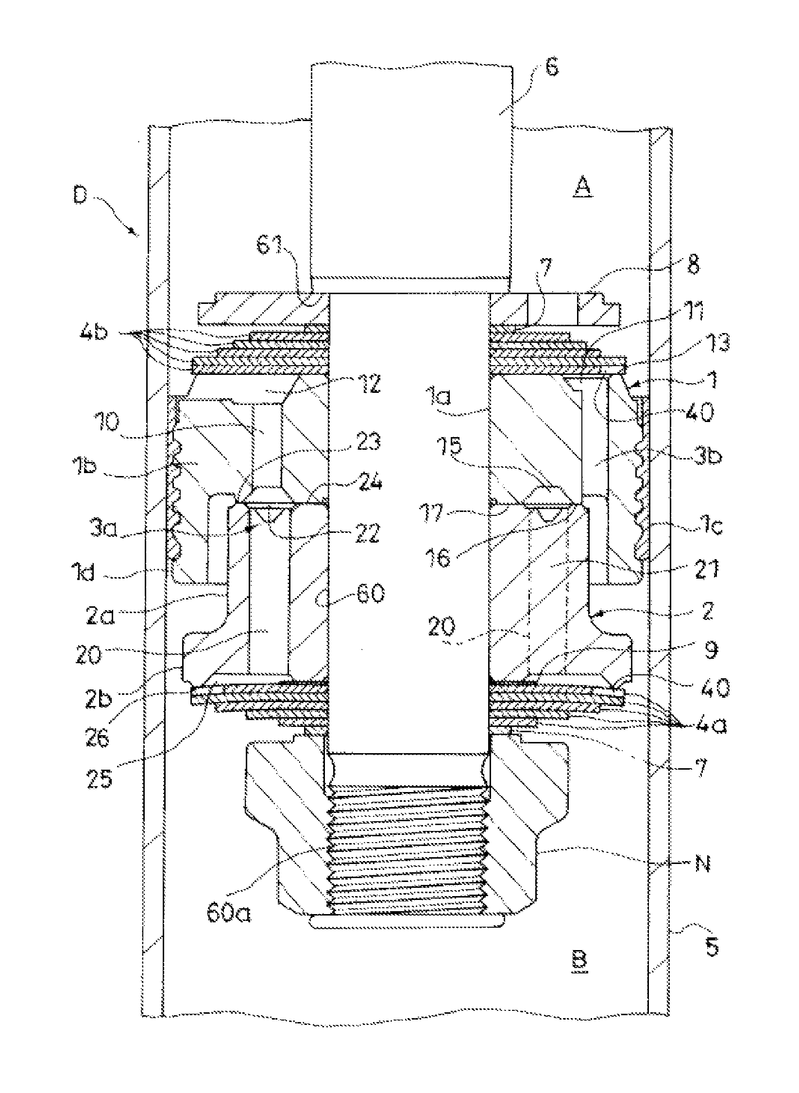
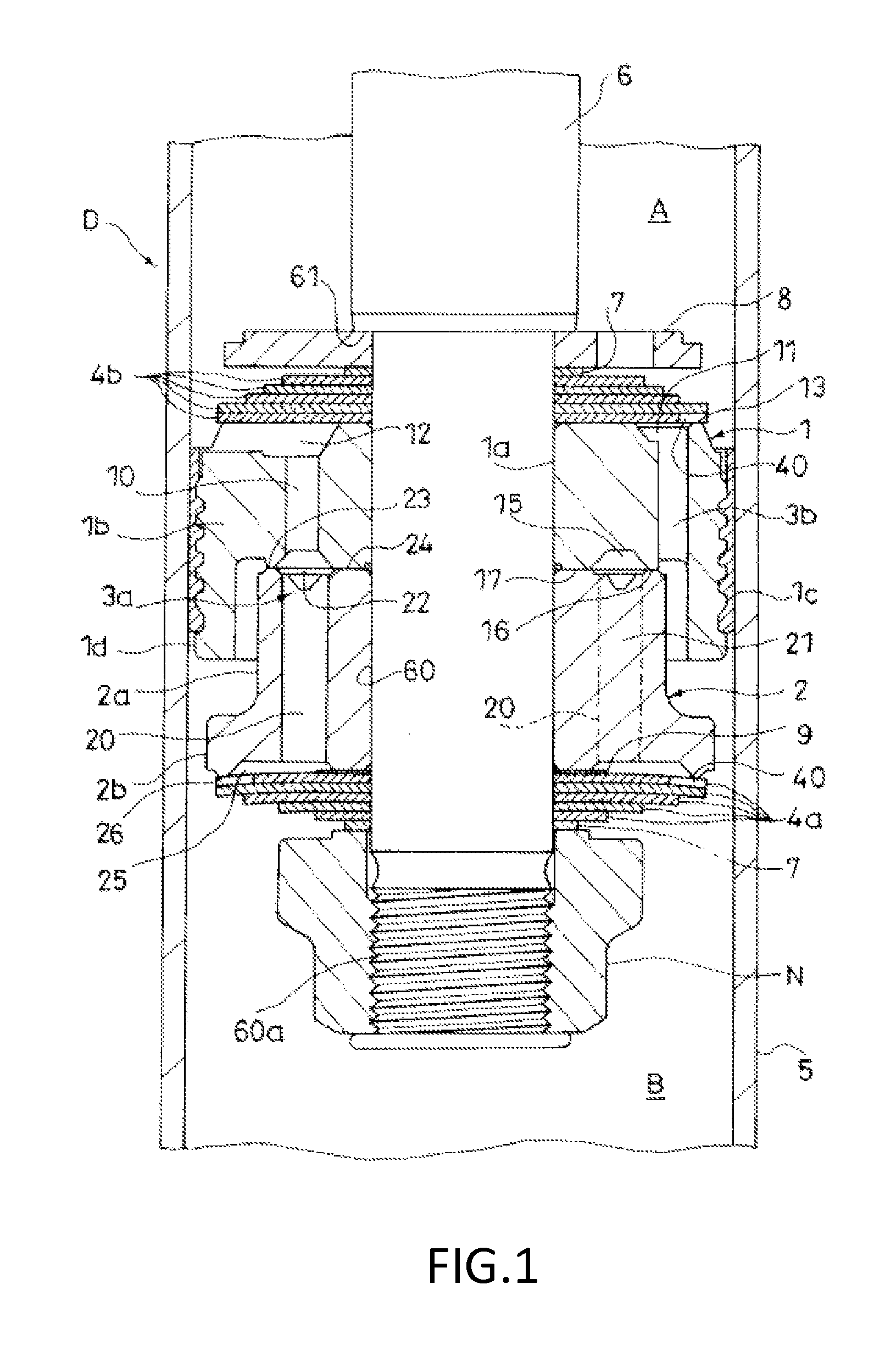
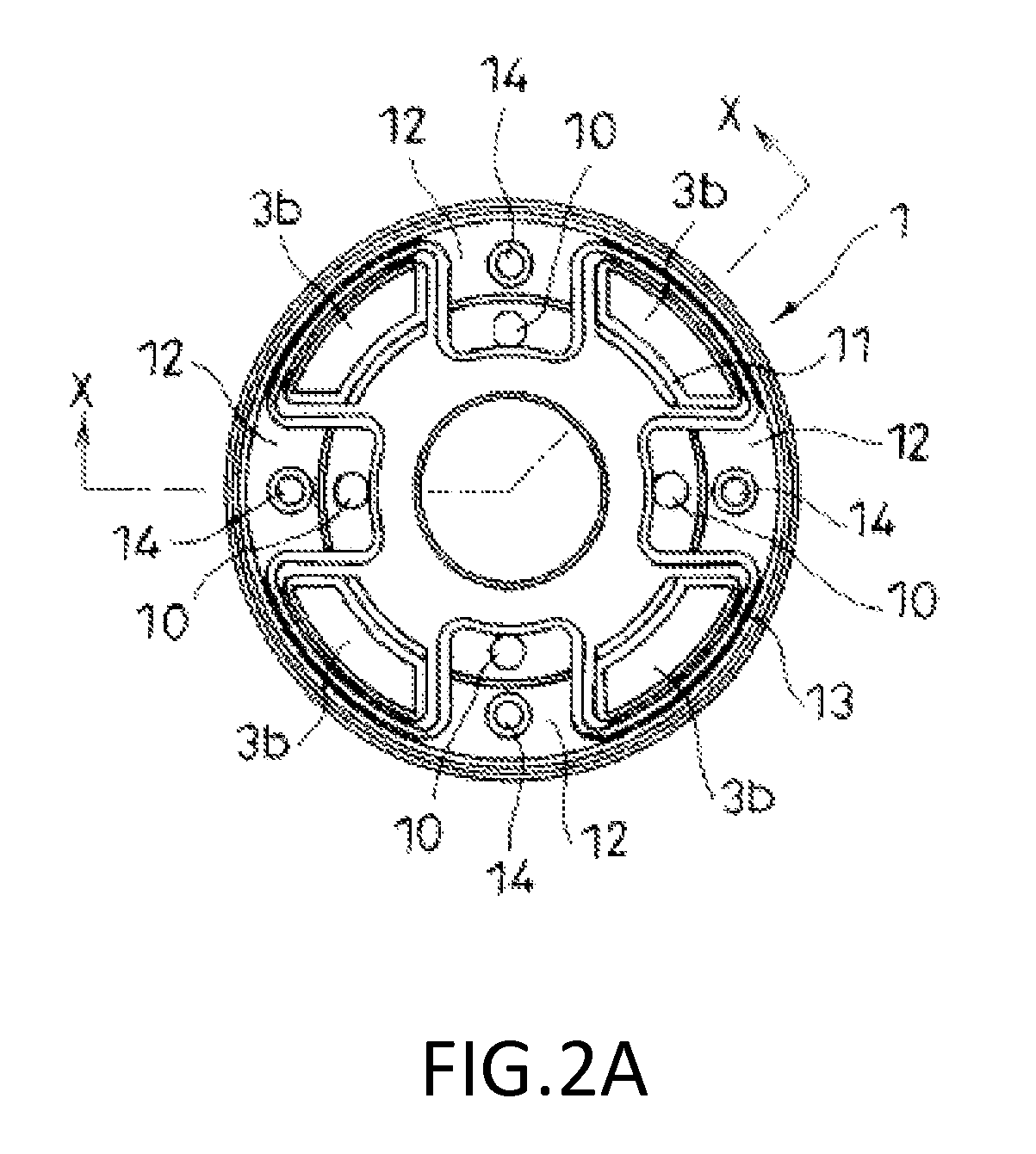
[0024]As shown in FIG. 1, a damping valve according to the present embodiment is applied to a piston unit of a shock absorber D and provided with a piston (valve disk) 1 partitioning one chamber A and another chamber B, a retainer 2 provided to be placed on the piston 1, an inner peripheral side flow passage 3a configured to include valve disk through holes 10 formed in an inner peripheral side of the piston 1 and retainer through holes 20 formed in the retainer 2 and allowing communication between the one chamber A and the other chamber B, outer peripheral side flow passages 3b formed in an outer peripheral side of the piston 1 and allowing communication between the one chamber A and the other chamber B, and leaf valves 4a in the form of annular plates arrang...


PUM


Abstract

A damping valve includes a valve disk, a retainer, an inner peripheral side flow passage configured to include a valve disk through hole formed in an inner peripheral side of the valve disk and a retainer through hole formed in the retainer and allowing communication between one and other chambers, an outer peripheral side flow passage formed in an outer peripheral side of the valve disk and allowing communication between the one and the other chambers, and a leaf valve in the form of an annular plate arranged on a side of the retainer opposite to the valve disk and configured to openably close the inner peripheral side flow passage by an outer peripheral part. A flow passage area of the retainer through hole is not smaller than that of the valve disk through hole.

Description

TECHNICAL FIELD[0001]The present invention relates to a damping valve for shock absorber.BACKGROUND ART[0002]A damping valve for shock absorber is applied, for example, to a piston unit or the like of a shock absorber for vehicle and is provided with a piston (valve disk) partitioning one chamber and another chamber for storing working fluid in the shock absorber, a flow passage formed in this piston to allow communication between the one and the other chambers, and a damping force generating element such as a leaf valve for applying resistance to the working fluid passing in this flow passage.[0003]When the piston moves toward the one or the other chamber, the one or the other chamber is pressurized and the working fluid moves between the one and the other chambers through the flow passage. In this way, the shock absorber generates a damping force due to the resistance of the damping force generating element.[0004]Since the damping force generated by the shock absorber for vehicle ...

Claims


Application Information

Patent Timeline
Patent Type & Authority Patents(United States)
IPC IPC(8): F16F9/348F16F9/32F16K15/14
CPCF16F9/3484F16F9/3214F16F9/3481F16K15/14F16F9/348
Inventor YAMADA, HIDEKI
Owner KYB CORP
Learn More