Inkjet printer

a printer and inkjet technology, applied in the field of inkjet printers, can solve the problems of adversely affecting the ejection performance and image quality, and achieve the effects of preventing the increase of the temperature inside the carriage, promoting drying, and preventing the reduction of the accuracy of ink landing

Active Publication Date: 2016-05-24
OKI DATA CORP
View PDF6 Cites 3 Cited by
  • Summary
  • Abstract
  • Description
  • Claims
  • Application Information

AI Technical Summary

Benefits of technology

[0012]The outside air taken by the device is taken into the carriage. Thus, the temperature inside the carriage is prevented from increasing, and the outside air not taken into the carriage cools the entire device. Further, the exhaust fan discharges the gas to the outside, and hence the recording medium is not cooled in a concentrated manner. Thus, the temperature of the ink immediately after the landing can be prevented from decreasing, and the drying can be promoted by moderately blowing air onto the recording medium after the printing. In addition, the air less flows around the nozzle surface of the recording head, thereby preventing reduction of ink landing accuracy, increase of ink mist, and drying of the nozzles.

Problems solved by technology

On the other hand, when the temperature of the recording head or the ink is changed, the viscosity of the ink is changed accordingly, which adversely affects the ejection performance and the image quality.

Method used


Image

  • Inkjet printer
  • Inkjet printer
  • Inkjet printer

Examples


Embodiment Construction

[0016]An embodiment of the present invention is described with reference to the drawings.

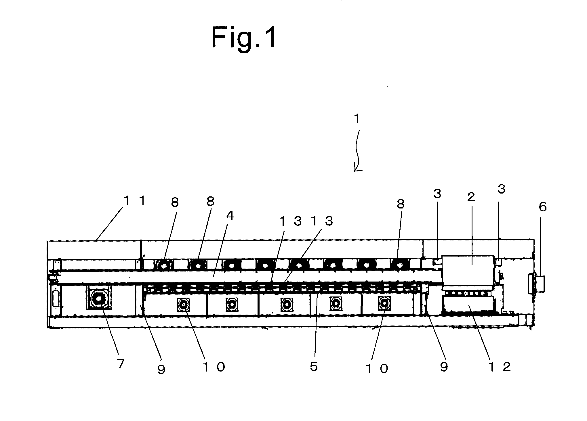
[0017]FIG. 1 is an explanatory view of the arrangement of suction means and exhaust means in an inkjet printer. A large number of housing-suction fans (first suction fans) 8 serving as housing-suction means for sucking a gas are provided in a rear surface of a housing 11 of an inkjet printer 1. The housing-suction fans 8 are arranged along a longitudinal direction of the housing 11. The housing-suction fans 8 suck an outside gas, that is, air into the housing 11.

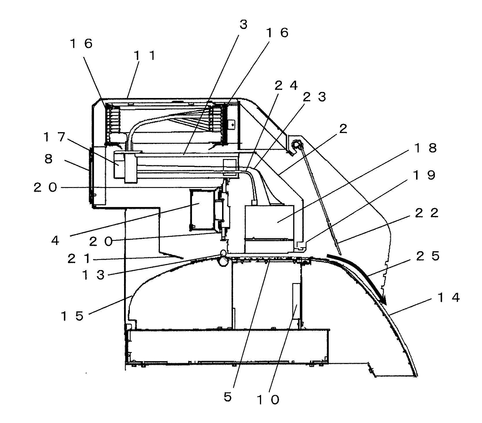
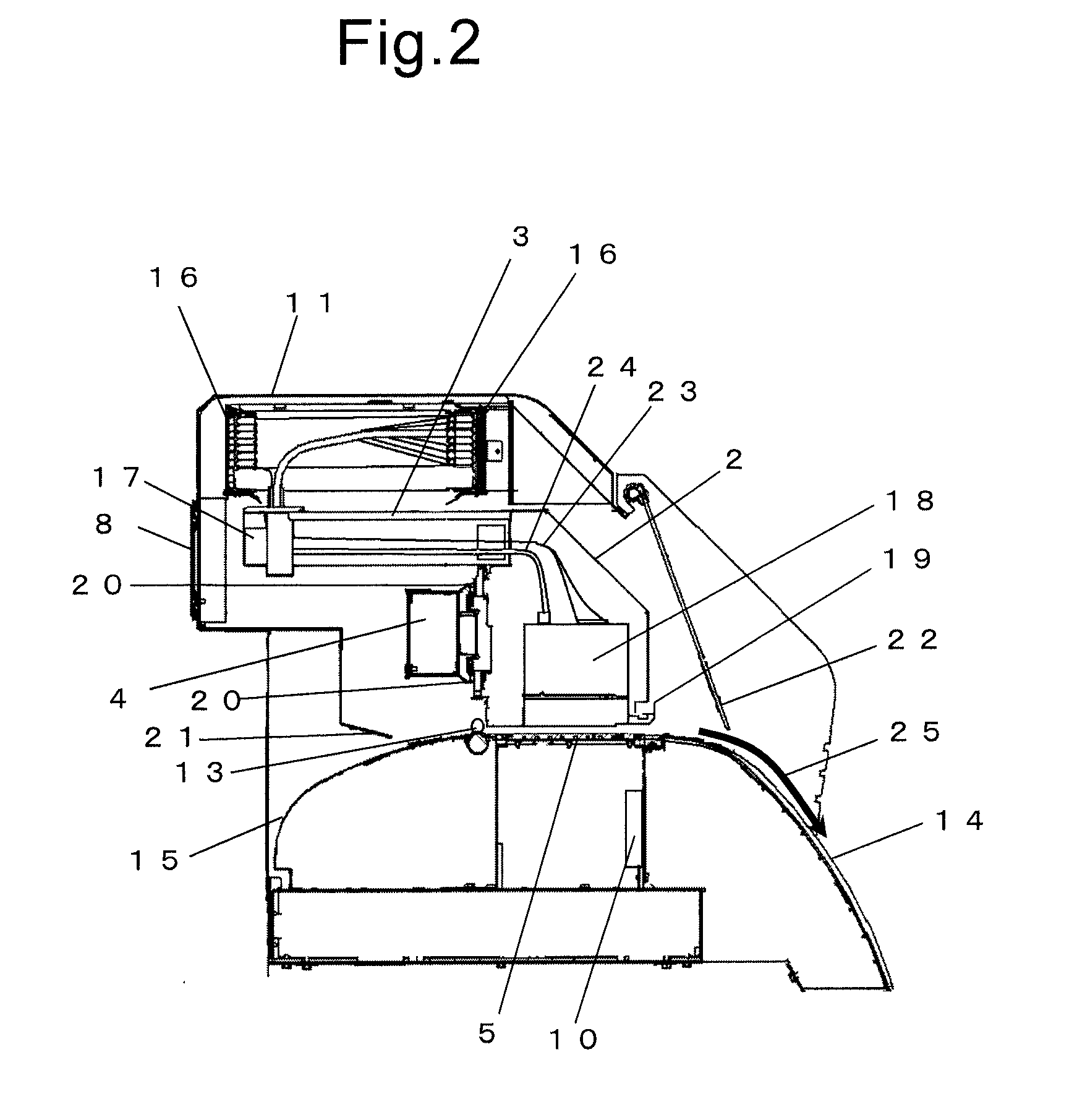
[0018]A Y rail 4 and a platen 5 are also arranged along the longitudinal direction of the housing 11. The platen 5 is a flat platen, and a large number of through holes are formed therein. Below the platen 5, there is secured a space partitioned by the platen 5, erecting plates 9 provided below both ends of the platen 5, and the like. A gas in the space is discharged to the outside through a large number of suction fans 10 so as to gener...


PUM


Abstract

An inkjet printer records an image on a recording medium by ejecting ink onto the recording medium from a recording head mounted on a carriage. A housing suction fan is arranged on a rear surface of the housing for sucking a gas from an outside into an inside of the housing. A carriage suction fan is arranged on the rear surface of the housing opposite to the housing suction fan for sucking into the carriage the gas sucked by the housing suction fan. A rear surface exhaust fan and a side surface exhaust fan are arranged on the rear surface and a side surface, respectively, of the housing for exhausting the gas inside the housing to the outside. The gas sucked by the housing suction fan is sucked into the carriage by the carriage suction fan and flows into the housing without being sucked by the carriage suction fan.

Description

BACKGROUND OF THE INVENTION[0001]1. Technical Field[0002]The present invention relates to an inkjet printer.[0003]2. Background Art[0004]There is known an inkjet printer for recording an image or the like by ejecting ink onto a recording medium, such as recording paper and a resin film. In the inkjet printer, various types of inks are used. Examples of the inks include solvent ink using an organic solvent as a prime solvent, ultraviolet curable ink that is curable due to ultraviolet radiation, and thermosetting ink that is curable due to heat. The various types of inks are used depending on intended use.[0005]In recent years, there has been a strong demand to promptly shift to a next work process, such as lamination so as to protect a printed surface after printing and cutting of a printed product into a desired size after the printing, thereby growing the demand to quickly dry the ink. To meet those demands, methods utilizing properties of inks, such as the ultraviolet curable ink ...

Claims


Application Information

Patent Timeline
Patent Type & Authority Patents(United States)
IPC IPC(8): B41J29/377B41J2/01B41J11/00
CPCB41J29/377B41J2/01B41J11/002B41J11/00244
Inventor SUZUKI, KENJI
Owner OKI DATA CORP
Why Eureka
Try Eureka