Vacuum pressure regulation system

a vacuum pressure and regulation system technology, applied in fluid pressure control, process and machine control, instruments, etc., can solve the problems of inability to achieve the desired exhaust velocity, inability to maintain the desired exhaust velocity of the vacuum chamber, and inability to reduce the pressure in the vacuum chamber, etc., to achieve accurate control, simplified structure, and accurate announcement

Active Publication Date: 2016-05-03
SMC CORP
View PDF26 Cites 5 Cited by
  • Summary
  • Abstract
  • Description
  • Claims
  • Application Information

AI Technical Summary

Benefits of technology

[0007]A technical object of the present invention is to provide a vacuum pressure regulation system capable of easily and securely deciding and announcing abnormality that may occur with the lapse of time, the system including a controller configured to control the aperture of a vacuum pressure regulating valve, to sequentially detect a difference between an actual pressure in a vacuum chamber and a target pressure thereby detecting the abnormality, in order to prevent failure to attain a desired exhaust velocity in the vacuum chamber because of the abnormality in the system when the vacuum pressure regulating valve is fully opened, and to announce the abnormality of the system when it is decided, on the basis of the detected difference, that the desired exhaust velocity is difficult to maintain with the valve aperture currently set.
[0009]Whereas the foregoing configuration is effective for reduction in size of the valve aperture adjusting unit 3 and improvement in responsiveness thereof since the output of the electric motor 45 that drives the adjuster 41 can be reduced, the present inventor has confirmed that the mentioned configuration allows the exhaust velocity to be adjusted to a value quite close to a preset evacuation velocity, thus to allow the exhaust gas in the vacuum chamber to be smoothly and generally linearly reduced. More specifically, FIG. 5 shows monitoring results (exhaust gas characteristics), in which the right vertical coordinate axis represents the exhaust velocity of the evacuation and the left vertical coordinate axis represents the pressure in the vacuum chamber at the preset velocity specified below under the foregoing configuration. Curved lines A1 and A2 in FIG. 5 respectively represent the monitoring results of the exhaust velocity in the case where the preset velocity of the exhaust gas was 1 Torr / s and 2 Torr / s, and curved lines B1 and B2 respectively represent the monitoring results of the pressure transition in the vacuum chamber in the case where the preset velocity of the exhaust gas was 1 Torr / s and 2 Torr / s. These monitoring results show that the foregoing configuration allows the exhaust velocity to be relatively accurately controlled in a generally constant range, thus to allow the pressure in the vacuum chamber to be generally linearly reduced.
[0010]Another technical object of the present invention is to provide, on the basis of the aforementioned finding, a vacuum pressure regulation system capable of accurately announcing abnormality with a highly simplified structure, in which the vacuum pressure regulating valve includes a valve aperture adjusting unit that sets by using the electric motor the position of the adjuster for setting the aperture of the valve member, to thereby control the exhaust velocity relatively accurately, in other words in a generally constant range according to the preset evacuation velocity, and a tolerance range (for example, ±50% of the preset velocity) is specified with respect to the preset value of the exhaust velocity according to the performance level of the valve aperture adjusting unit, so that abnormality is detected in the case where the exhaust velocity deviates from the tolerance range, or where another value such as the valve aperture deviates from the corresponding tolerance range.
[0019]Accordingly, the pressure-receiving member is driven by the pilot fluid pressure to the position where the pressure-receiving member is pressed against the adjuster with a generally constant force, to be constantly pressed against the adjuster with the biasing force. Such a situation allows the acting force of the return spring and the acting force based on the pressure in the vacuum chamber exerted on the valve member to be offset with the pilot fluid pressure exerted on the pressure-receiving member, thereby exempting the electric motor from having a driving force that can cope with the mentioned acting forces and thus enabling a small-sized electric motor having a low output power to be employed.
[0022]Further, as simple substitution for the pilot fluid pressure control, the acting force of the return spring and the acting force based on the pressure in the vacuum chamber exerted on the valve member may be measured in advance, and these values may be functionized on the basis of the correlation between the position of the pressure-receiving member and the acting forces and stored in the controller. Such an arrangement allows the pilot fluid pressure supplied to the pressure-receiving chamber to be uniquely determined according to the position of the valve member, which eliminates the need to detect whether the driving current supplied to the electric motor is between the predetermined upper limit and the lower limit.
[0025]In particular, the exhaust velocity can be relatively accurately controlled according to the preset evacuation velocity, by providing the vacuum pressure regulating valve with the valve aperture adjusting unit that sets the position of the adjuster by using the electric motor on the basis of the finding that the exhaust velocity can be maintained in a generally constant range through the pilot fluid pressure control with the electromagnetic valve unit, which maintains the rotational load of the electric motor based on the pressing force between the pressure-receiving member and the adjuster in the range between the predetermined upper limit and the lower limit. Accordingly, the abnormality can be accurately announced with a highly simplified structure by specifying a tolerance range with respect to the preset value of the exhaust velocity according to the performance level of the valve aperture adjusting unit, and deciding the abnormality in the case where the exhaust velocity deviates from the tolerance range. Further, the abnormality can also be accurately announced with a highly simplified structure, by uniquely determining the pilot fluid pressure to be supplied to the pressure-receiving chamber according to the position of the valve member, on the basis of the information of the acting force of the return spring and so forth functionized in advance.

Problems solved by technology

With the vacuum pressure regulation system thus configured, however, a valve aperture preset in advance may fail to maintain the desired exhaust velocity in the case where abnormality such as leak in the vacuum chamber or other points in the vacuum system or clogging of a piping takes place, in which case the controller executes a feedback control so as to increase the valve aperture on the basis of comparison between an output of a pressure sensor that detects the pressure in the vacuum chamber and a signal of a control command such as an externally specified pressure or transition of the exhaust velocity.
Nevertheless, the pressure in the vacuum chamber is unable to be lowered while the abnormality remains unremoved, and therefore the valve is finally set to the maximum aperture by the feedback control, still failing to attain the desired exhaust velocity.
If the vacuum pump continues to aspirate gas of a high temperature from the vacuum chamber while the vacuum pressure regulating valve remains fully opened, the piping may be damaged and even the vacuum pump may be broken down, in which case an enormous cost and time is required for restoring the system.
However, the decision of the abnormality made by the vacuum pressure control system according to Patent Literature 2 is with respect to a pinpoint in the transition of the valve aperture, and does not lead to the conclusion whether the evacuation is being normally and continuously performed.
Moreover, the pinpoint aperture and setting of a pressure correlated thereto involve various experimental factors, and therefore it is difficult to set an appropriate value through a simple process, and further the transition of the aperture with time is unable to be ascertained.

Method used


Image

  • Vacuum pressure regulation system
  • Vacuum pressure regulation system
  • Vacuum pressure regulation system

Examples


Embodiment Construction

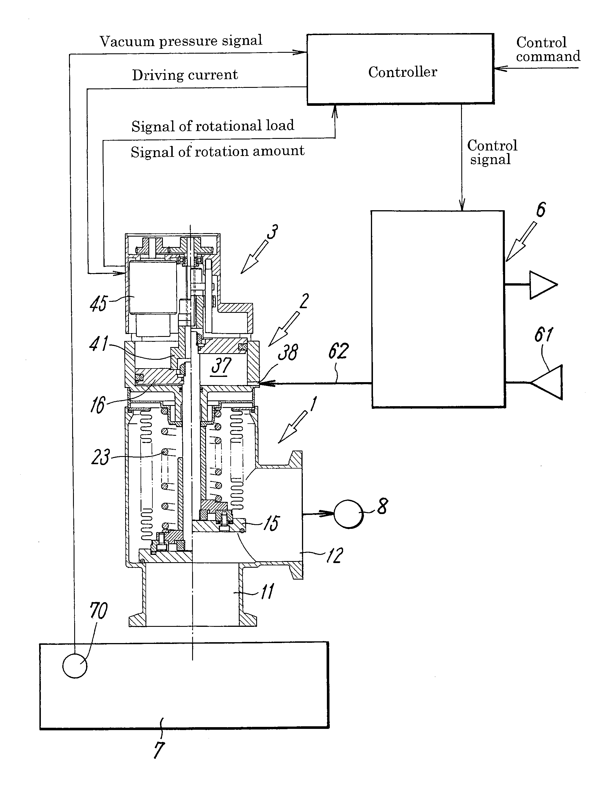
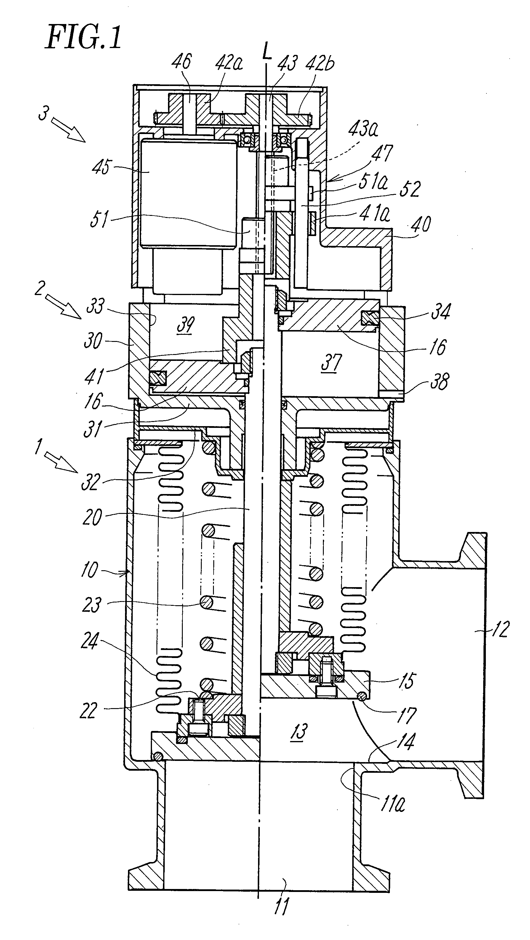
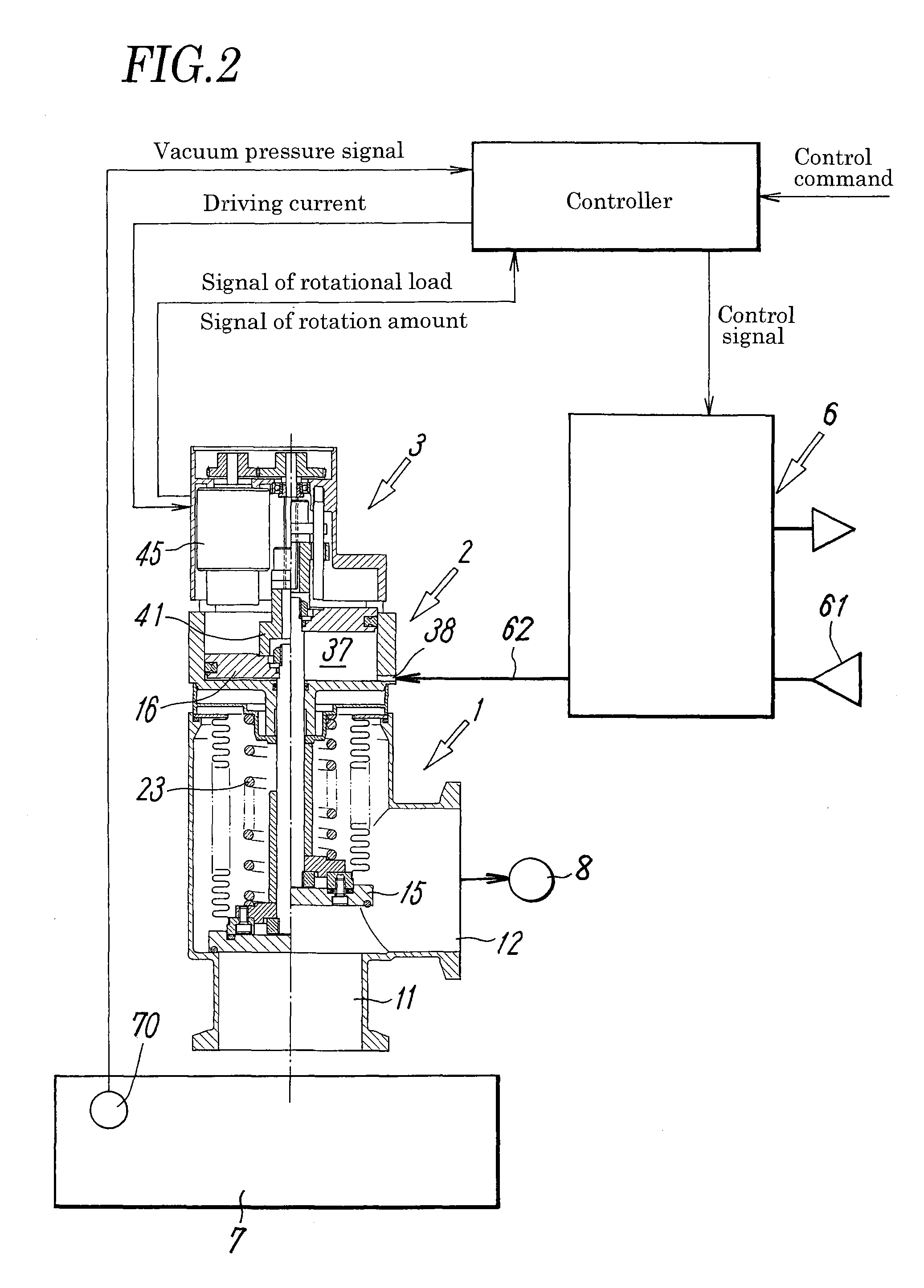
[0031]FIG. 1 illustrates a typical embodiment of a vacuum pressure regulating valve employed in a vacuum pressure regulation system according to the present invention, and FIG. 2 illustrates a general configuration of the vacuum pressure regulation system including the vacuum pressure regulating valve.

[0032]The vacuum pressure regulating valve includes a valve main body 1 having a valve member 15 that opens and closes a flow path 13 between a first and a second main ports 11, 12, a fluid pressure driving unit 2 having a piston (pressure-receiving member) 16 that opens and closes the valve member 15, and a valve aperture adjusting unit 3 that sets the aperture of the valve member 15. The vacuum pressure regulating valve is connected, as shown in FIG. 2, to an electromagnetic valve unit 6 that supplies and discharges a pilot fluid to and from the fluid pressure driving unit 2, and to a controller that receives a control command and information of a load of an electric motor 45 to be d...


PUM


Abstract

A valve main body including a valve member that opens and closes a valve seat is associated with a fluid pressure driving unit including a pressure-receiving member (piston) that drives the valve member, a valve aperture adjusting unit that sets the aperture of the valve member, an electromagnetic valve unit that supplies and discharges a pilot fluid to and from the fluid pressure driving unit, and a controller that controls the aperture of the valve member. The controller controls the aperture of the valve member by controlling the position of the pressure-receiving member, such that the vacuum chamber attains a predetermined target pressure, and monitors a difference between an actual pressure in the vacuum chamber obtained from the pressure sensor and the target pressure, and announces abnormality in the case where the difference deviates from a tolerance range.

Description

TECHNICAL FIELD[0001]The present invention relates to a vacuum pressure regulation system to be used for depressurizing a vacuum chamber for chemical reaction in a physicochemical apparatus or the like.BACKGROUND ART[0002]In a manufacturing apparatus of a semiconductor, for example, physicochemical treatment is performed in a vacuum chamber. In this process a vacuum pressure regulating valve is employed for opening and closing a flow path connecting between the vacuum chamber and a vacuum pump that depressurizes the vacuum chamber and, normally, a vacuum pressure regulation system is constituted including a controller that gradually increases the aperture of the valve to prevent particles from being dispersed inside the vacuum chamber.[0003]The vacuum pressure regulating valve includes, for example as disclosed in Patent Literature 1, Japanese Unexamined Patent Application Publication No. 2007-146908, a valve main body including, inside a valve housing in which a valve seat is provi...

Claims


Application Information

Patent Timeline
Patent Type & Authority Patents(United States)
IPC IPC(8): G05D16/20
CPCG05D16/2086G05D16/2093Y10T137/7761G05D16/024G05D16/2097F16K31/04F16K31/124F16K37/00F16K51/02
Inventor WATANABE, TADAOHIRABAYASHI, YU
Owner SMC CORP
Why Eureka
Try Eureka