
Connection device for connecting an electronic component to a housing part and electronic controller

Active Publication Date: 2016-04-26
KNORR-BREMSE SYST FUER NUTZFAHRZEUGE GMBH
View PDF21 Cites 2 Cited by
  • Summary
  • Abstract
  • Description
  • Claims
  • Application Information

AI Technical Summary

Benefits of technology

[0019]It is particularly advantageous if the first bush and the second bush are arranged offset relative to one another. This facilitates assembly and prevents parts of the fastening units from coming into heat-transmitting contact with one another in an outer area via another, heat-conducting, component arranged there.
[0020]According to a development, the first and the second bush are arranged offset relative to one another with respect to a common receiving direction for receiving the first fastening unit and the second fastening unit respectively. This counteracts an effect that ends of the fastening units, such as screw or bolt heads, protruding on one side (e.g. the side from which the fastening units are introduced into the bushes during assembly) simultaneously come into heat-conducting contact with a hot component and thus produce a heat-conducting connection.
[0021]It is particularly advantageous if the electronic component includes an electronic circuit carrier, in particular a circuit board. It is a simple matter to accommodate and mount complex circuits on such a circuit board. A substrate of the circuit board can serve as the carrier. However, it is also possible to use an additional carrier.
[0022]A cooler is preferably provided for cooling the electronic component. In this way, it is possible to keep the electronic component at a low operating temperature, especially in high temperature environments, thereby increasing its performance and service life. The cooler can be formed from a material

Problems solved by technology

One of the restricting factors in the use of electronic components and controllers in high-temperature applications, e.g. in the area of vehicles and commercial vehicles and the control thereof, is the temperature of the electronic components used.
The electronic compone

Method used


Image

  • Connection device for connecting an electronic component to a housing part and electronic controller
  • Connection device for connecting an electronic component to a housing part and electronic controller

Examples


Example

DETAILED DESCRIPTION OF THE DRAWINGS

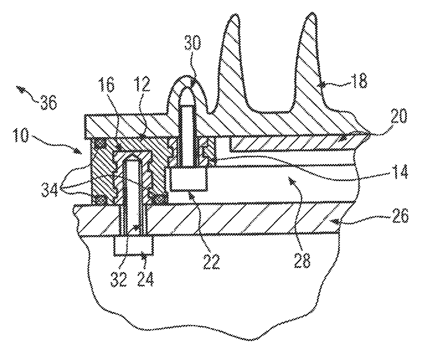
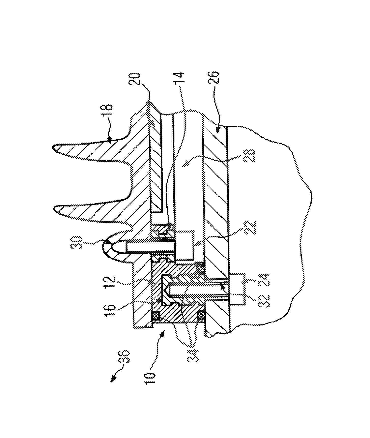
[0028]FIG. 1 shows a connection device 10. The connection device 10 includes a frame 12 produced from plastic. The frame 12 has a first bush 14 and a second bush 16. Provision can be made for the frame 12 to be produced in an injection molding process, in which the bushes 14 and 16 are encapsulated with frame material. For reasons of stability, the bushes 14 and 16 are produced from a metallic material. As can be seen, the bushes 14, 16 have undercuts in order to achieve good retention in the frame 12. It is also contemplated to produce one or both bushes 14, 16 from some other material or to mold the frame 12 directly in such a way that shapes corresponding to the bushes are obtained to receive fastening units. The first bush 14 is designed in such a way that it offers an opening which passes through the frame 12. The second bush 16, in contrast, is closed at an end situated within the frame 12. Both bushes 14, 16 can have a thread.

[0029]FIG. 1 f...


PUM


Abstract

A connection device is provided connecting an electronic component that is arranged on a carrier to a housing part. The connection device has a first bush for receiving a first fastening unit which is used to fasten the connection device to the carrier and a second bush for receiving a second fastening unit for fastening the connection device to the housing part. The first bush is thermally insulated from the second bush. A controller has an electronic component which is arranged on the carrier and which is connected or can be connected to the housing part by use of such a connection device.

Description

CROSS-REFERENCE TO RELATED APPLICATIONS[0001]This application is a continuation of PCT International Application No. PCT / EP2011 / 053143, filed Mar. 3, 2011, which claims priority under 35 U.S.C. §119 from German Patent Application No. 10 2010 010 926.6, filed Mar. 10, 2010.BACKGROUND AND SUMMARY OF THE INVENTION[0002]The present invention relates to a connection device for connecting an electronic component arranged on a carrier to a housing part. The invention furthermore relates to an electronic controller having an electronic component, which is arranged on a carrier and is connected or can be connected to a housing part by means of a connection device.[0003]One of the restricting factors in the use of electronic components and controllers in high-temperature applications, e.g. in the area of vehicles and commercial vehicles and the control thereof, is the temperature of the electronic components used. The electronic components function in a particularly efficient way at low tempe...

Claims


Application Information

Patent Timeline
IPC IPC(8): H05K7/14H05K7/20F16B43/00F16B33/00
CPCH05K7/14F16B33/004F16B43/001H05K7/1417H05K7/20854
Inventor EICHNER, MARKUSUHLAND, THOMAS
Owner KNORR-BREMSE SYST FUER NUTZFAHRZEUGE GMBH
Learn More