
Compact lens system and array

a compact lens and array technology, applied in the field of submicron resolution imaging, can solve the problems of large physical size of many microscopes, high cost and bulky, and rely on multi-element objective lenses, and achieve low cost, high resolution, and wide field of view imaging

Active Publication Date: 2016-04-05
RGT UNIV OF MICHIGAN
View PDF3 Cites 26 Cited by
  • Summary
  • Abstract
  • Description
  • Claims
  • Application Information

AI Technical Summary

Benefits of technology

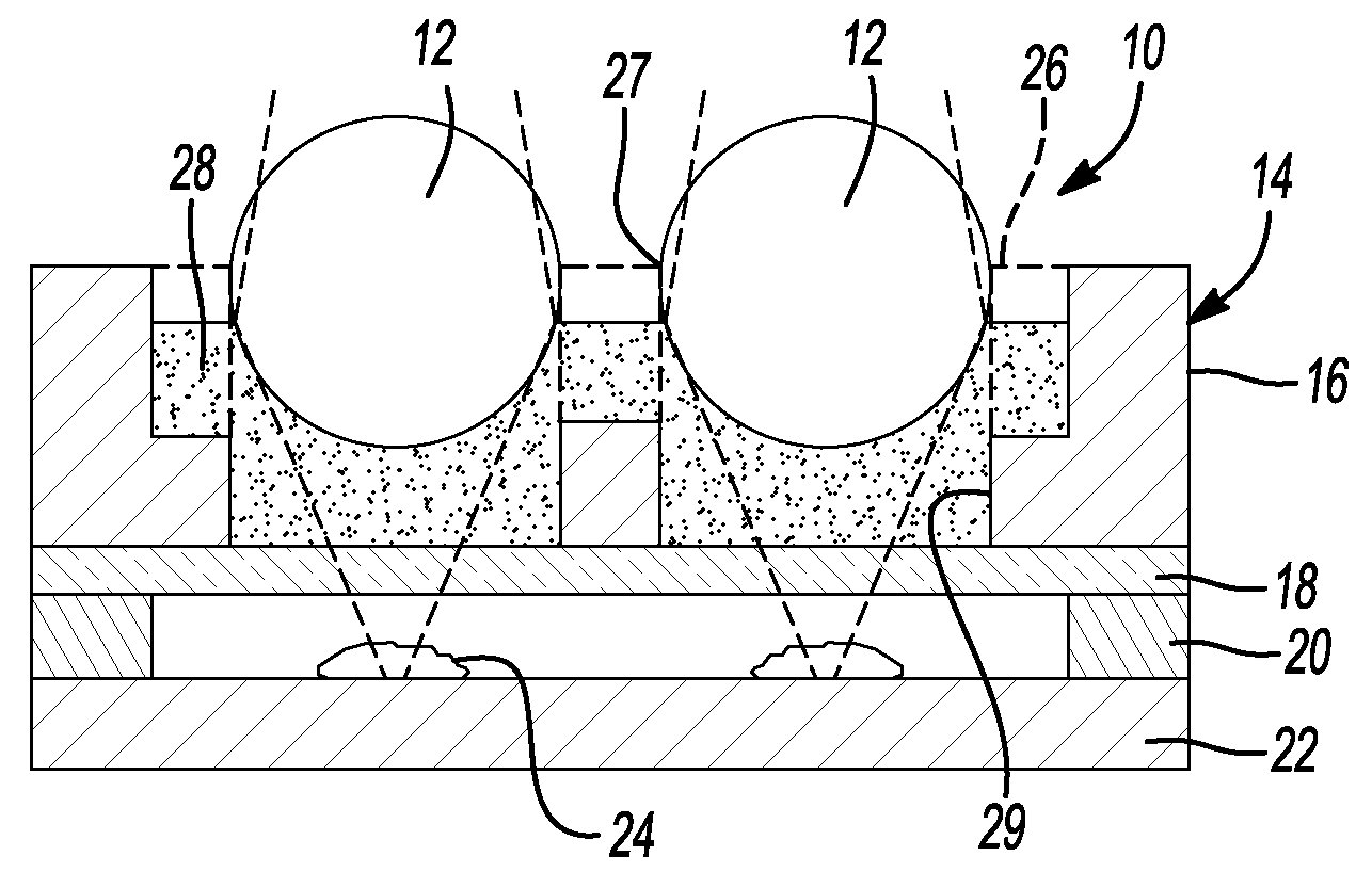
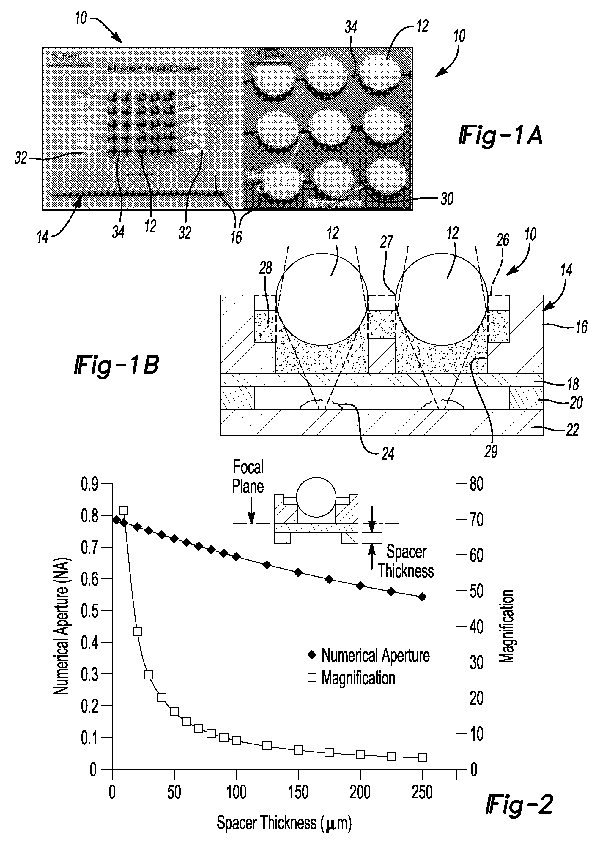
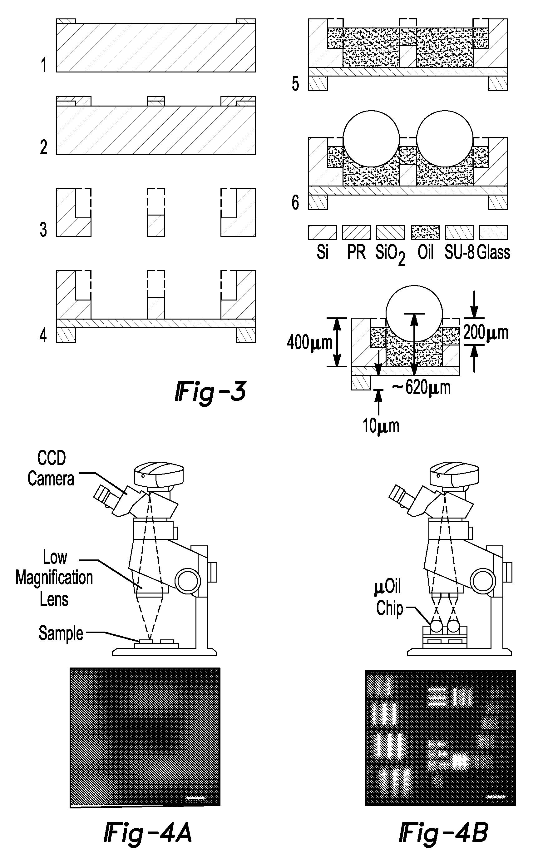
The present patent describes a new device that uses a low-cost, high-NA array of miniaturized ball lenses made of high index of refraction material to image biological samples. The lenses can be easily assembled and held in place on a microfabricated platform, which allows for easy scaling up to multiple wide field of view imaging. This compact lens system provides high resolution and high numerical aperture optical imaging capabilities, making it ideal for cell imaging and counting. The use of the entire lens array automates the counting process and eliminates statistical variations, and the device can be expanded for imaging other biological samples.

Problems solved by technology

High-end optical systems that achieve submicron resolution imaging rely on multi-element objective lenses that are expensive and bulky.
This is normally achieved by employing expensive high magnification immersion objectives for the microscopes, which can cost several thousand dollars each.
The large physical size of many microscopes is an impediment to making measurements in controlled environments, such as incubators or with living laboratory animals, such as mice, rats or guinea pigs.
This limitation prevents simultaneous observation of a large area of the sample with high resolution.
However, the resolution and image quality of the previous attempt at making simple imaging systems with ball lenses was not very successful—maximum resolution achieved was greater than one micron and the image quality was poor due to its construction.
However, the cost of these systems was prohibitively high.

Method used


Image

  • Compact lens system and array
  • Compact lens system and array
  • Compact lens system and array

Examples


Embodiment Construction

[0044]Example embodiments will now be described more fully with reference to the accompanying drawings. Example embodiments are provided so that this disclosure will be thorough, and will fully convey the scope to those who are skilled in the art. Numerous specific details are set forth such as examples of specific components, devices, and methods, to provide a thorough understanding of embodiments of the present disclosure. It will be apparent to those skilled in the art that specific details need not be employed, that example embodiments may be embodied in many different forms and that neither should be construed to limit the scope of the disclosure. In some example embodiments, well-known processes, well-known device structures, and well-known technologies are not described in detail.

[0045]The terminology used herein is for the purpose of describing particular example embodiments only and is not intended to be limiting. As used herein, the singular forms “a,”“an,” and “the” may b...


PUM

PropertyMeasurementUnit
refractive indexaaaaaaaaaa

Abstract

A compact lens system for imaging a sample comprising a substrate having a well formed therein. Index matching material is disposed in the well and a lens member is further disposed in the well in optical contact with the index matching material disposed in the well. A spacer member extends from at least one of the substrate and the lower transparent member to define a spacing from a focal point of the lens member, wherein the lens member and index matching material cooperate to image a sample disposed below the lower transparent member.

Description

CROSS-REFERENCE TO RELATED APPLICATIONS[0001]This application claims the benefit of U.S. Provisional Application No. 61 / 781,944, filed on Mar. 14, 2013. The entire disclosure of the above application is incorporated herein by reference.GOVERNMENT INTEREST[0002]This invention was made with government support under OD006458 awarded by the National Institutes of Health. The government has certain rights in the invention.FIELD[0003]The present disclosure relates generally to imaging and, more particularly, relates to submicron resolution imaging of bacteria, cells, microorganisms, whole tissue, and the like in bright field, dark field and fluorescent image modes in multiple locations simultaneously using a compact lens system and array.BACKGROUND AND SUMMARY[0004]This section provides background information related to the present disclosure which is not necessarily prior art. This section also provides a general summary of the disclosure, and is not a comprehensive disclosure of its ful...

Claims


Application Information

Patent Timeline
Patent Type & Authority Patents(United States)
IPC IPC(8): G02B7/02G01N21/64G01N15/14G02B3/00G02B21/36G02B21/33
CPCG02B7/027G01N15/1436G01N21/6458G02B3/0056G02B21/365G01N2201/0639
Inventor GULARI, MAYURACHAT NINGGHANNAD-REZAIE, MOSTAFATRIPATHI, ANURAGCHRONIS, NIKOLAOS
Owner RGT UNIV OF MICHIGAN
Learn More