
Variable stiffness guidewire systems and methods

a guidewire and variable stiffness technology, applied in the direction of guide wires, catheters, etc., can solve the problems of time-consuming and burdened by the cost of additional guidewires, and achieve the effect of desired stiffness

Inactive Publication Date: 2016-03-29
WRIGHT AHN TECH
View PDF68 Cites 5 Cited by
  • Summary
  • Abstract
  • Description
  • Claims
  • Application Information

AI Technical Summary

Benefits of technology

The system reduces the need for multiple guidewires by allowing a single guidewire to be adjusted to various stiffness levels, thereby decreasing procedure time and cost while maintaining access capabilities.

Problems solved by technology

While guidewire exchanges are well accepted, they are time consuming and burdened by the cost of the additional guidewires.

Method used


Image

  • Variable stiffness guidewire systems and methods
  • Variable stiffness guidewire systems and methods
  • Variable stiffness guidewire systems and methods

Examples


Embodiment Construction

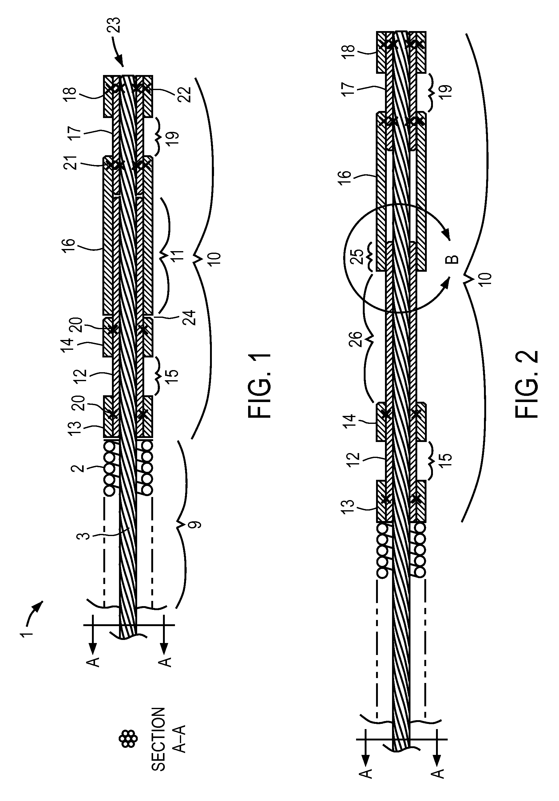
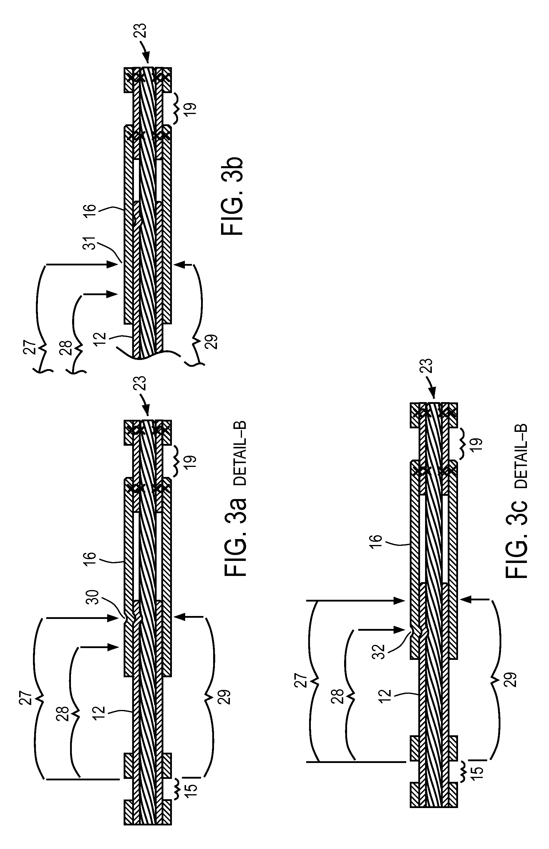
[0029]Disclosed herein are guidewires, actuators, and methods of using the guidewires and actuators that allow a user to select and maintain different guidewire stiffness characteristics such that a single guidewire can address a range of access capabilities currently requiring multiple guidewires.

[0030]An embodiment of the invention will now be described in detail with reference to FIG. 1. FIG. 1 shows the proximal region of a guidewire 1 according to one embodiment of the invention. The guidewire 1 includes a guidewire body 9. Guidewire 1 may be or include features similar to the guidewires described in co-pending application Ser. Nos. 12 / 192,946 and 12 / 192,950, both titled “Variable Stiffness Guidewire Systems” and both filed on Aug. 15, 2008, the entireties of which are hereby incorporated by reference.

[0031]The proximal region of guidewire 1 shown in FIG. 1 also includes an actuation interface 10 positioned at a proximal end of the guidewire body 9. The actuation interface 10 i...


PUM


Abstract

Guidewires, actuators and methods of using the guidewires and actuators are described. These tools and methods allow a user to select and maintain different guidewire stiffness characteristics such that a single guidewire can address a range of access capabilities.

Description

BACKGROUND[0001]1. Field[0002]The subject invention relates to variable stiffness guidewire systems and methods.[0003]2. Related Art[0004]Guidewires of different stiffness characteristics provide users with a range of capabilities to gain and maintain access during diagnostic and interventional procedures. The capabilities required are dependent on variables including, but not limited to, patient anatomy, placement target, tools to be placed, and physician preference. Accordingly, it is commonplace and often necessary to perform one or more guidewire exchanges during these procedures.[0005]While guidewire exchanges are well accepted, they are time consuming and burdened by the cost of the additional guidewires. Thus, there is a need to reduce or eliminate the need for guidewire exchanges to reduce procedure time and cost.SUMMARY[0006]The following summary of the invention is included in order to provide a basic understanding of some aspects and features of the invention. This summar...

Claims


Application Information

Patent Timeline
Patent Type & Authority Patents(United States)
IPC IPC(8): A61M25/09
CPCA61M25/09A61M25/09033A61M2025/0915A61M2025/09083A61M2025/09116
Inventor WRIGHT, JAY, RALPHAHN, SAMUEL, SEUNGHAEASHBY, MARK, PHILIP
Owner WRIGHT AHN TECH
Learn More