Gas cell for the optical analysis of gases

a gas analysis and gas cell technology, applied in the direction of optical radiation measurement, instruments, spectrometry/spectrophotometry/monochromators, etc., can solve the problems of increasing the exchange time, the time resolution and therefore the conflicting objectives of detection sensitivity, and the dynamic response to decrease correspondingly, so as to improve the dynamic response of the measuring cell and achieve fast gas exchange , the effect of small siz

Active Publication Date: 2016-03-08
CHEVROU USA INC +1
View PDF1 Cites 1 Cited by
  • Summary
  • Abstract
  • Description
  • Claims
  • Application Information

AI Technical Summary

Benefits of technology

[0014]The inventive measuring cell has a shape that is optimally adapted to the formation of a vortex at the inlet of the sample gas and the transformation of the vortex as it moves toward the outlet and in such a way that the flow of gas that moves from the inlet to the outlet fills the entire cell volume along a direct path. The emphasis here is on a direct path, i.e. secondary curls or other fluidic figures do not have to be formed to exchange the gas in remote zones (dead zones). Indeed, the inventive shape avoids the existence of such dead zones, resulting in particularly fast gas exchange due to the exchange along a direct path.
[0015]The invention has recognized that the dynamic response of the measuring cell can be improved not only with a particularly small size of the cell volume but, in contrast to previous attempts in prior art, also with a larger size of measuring cell having a special shape. This special shape is provided by the ovality on the inlet side, which disappears toward the outlet. As has already been mentioned, this special shape allows a particularly fast exchange of gas and produces the desired improvement in the dynamic response. This invention therefore no longer relies on an especially small size of measuring cell, enabling the measuring cell to be larger and therefore more robust. This lengthens the optical path for the measuring beam and these good optical conditions improve detectability of the measuring cell. The invention therefore achieves a combination of advantages with respect to improved dynamic response and improved detectability. It achieves this in a surprisingly simple way, namely solely by ingenious shaping of the measuring cell. There is no example of this in prior art.
[0016]To reliably achieve favorable vortex formation even as the sample gas flows in, the inlets are preferably disposed in the tube casing. Disposing them thereby in the region of the start of the tube has the advantage, compared to positioning on the start end face, that reliable and flow-advantageous main vortex formation can be achieved. This particularly applies when the inlets are disposed diametrically opposite each other, and offset with respect to the central axis of the tube shape. This not only applies if two inlets are provided but also if more than two inlets are provided: in this case, they should be disposed in such a way that the sample gas initially flows into the tube tangentially. With this configuration, the inflowing sample gas can be induced to swirl. This results in stabilization of the flow and ensures the desired penetration of the entire inner chamber volume with the main vortex.
[0017]The outlets for the exiting sample gas are preferably constituted with an axial component. This is understood to mean that the outlets have an angle of maximum 30° with respect to the tube axis. Disposing them on the casing allows the mirror for the measuring beam to be disposed in the center. In this way, the end region can be optimally used for generating the optical path for the measuring beam. Furthermore, this outlet configuration has the advantage that unimpeded exit of the gas can be achieved due to the considerable tangential component. The outlets are preferably tapered. This is understood to mean that at their start, i.e. in the region of their entry, they have the largest cross-section, which successively tapers the further it is from the inner chamber. It has been shown that a particularly good discharge characteristic from the inner chamber into the outlet of the sample gas can be achieved in this way, particularly with respect to the paucity or absence of reflections and the vortex or antivortex caused by them.

Problems solved by technology

This results in a conflict of objectives between detection sensitivity and the time resolution of the system.
Increasing the volume of the measuring cell therefore has the disadvantage that, while other parameters remain constant, the time required to completely replace the gas increases, causing the time resolution and therefore the dynamic response to decrease correspondingly.
In such a measuring cell, however, relatively large “dead zones” are formed, which increase the exchange time and worsen the dynamic response.
The resulting time delay causes carryover (concentration carryover), which in turn results in a long response time of the measuring cell and therefore of the entire measuring system.

Method used


Image

  • Gas cell for the optical analysis of gases
  • Gas cell for the optical analysis of gases
  • Gas cell for the optical analysis of gases

Examples


Embodiment Construction

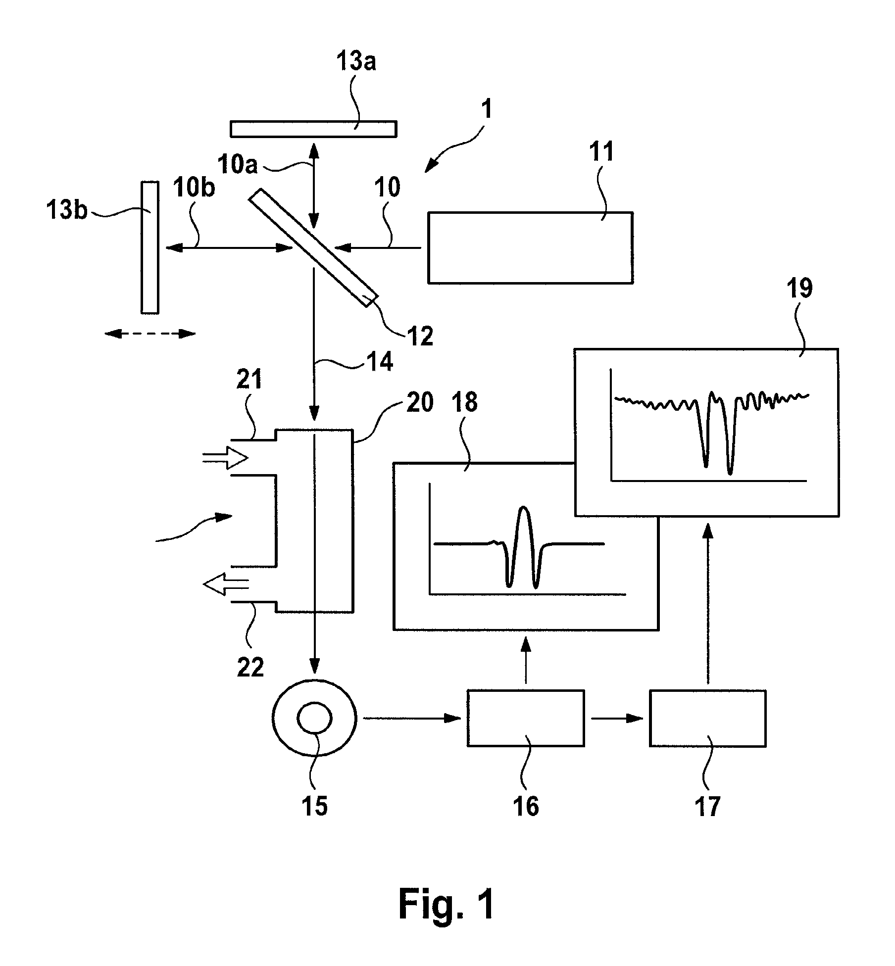
[0031]The invention is explained using the example of an FTIR spectrometer. FTIR stands for Fourier transform infrared spectroscopy. Such devices are known from prior art and will therefore be only briefly explained with reference to FIG. 1.

[0032]An infrared light beam 10 (IR beam) from a source 11 for infrared radiation is focused onto an obliquely disposed beam splitter 12 of an interferometer, which is collectively designated by reference numeral 1. The IR beam 10 is divided into two components 10a and 10b, of which component 10a is reflected by the beam splitter 12 to a fixed mirror 13a, and component 10b is allowed to pass through to a movable mirror 13b, whose distance from the beam splitter 12 can be altered (symbolized by the dashed double-headed arrow in FIG. 1). The partial beams 10a, 10b reflected back by the mirrors 13a, 13b, interfere at beam splitter 12 and are together radiated as IR measuring beam 14 into a gas cell 2.

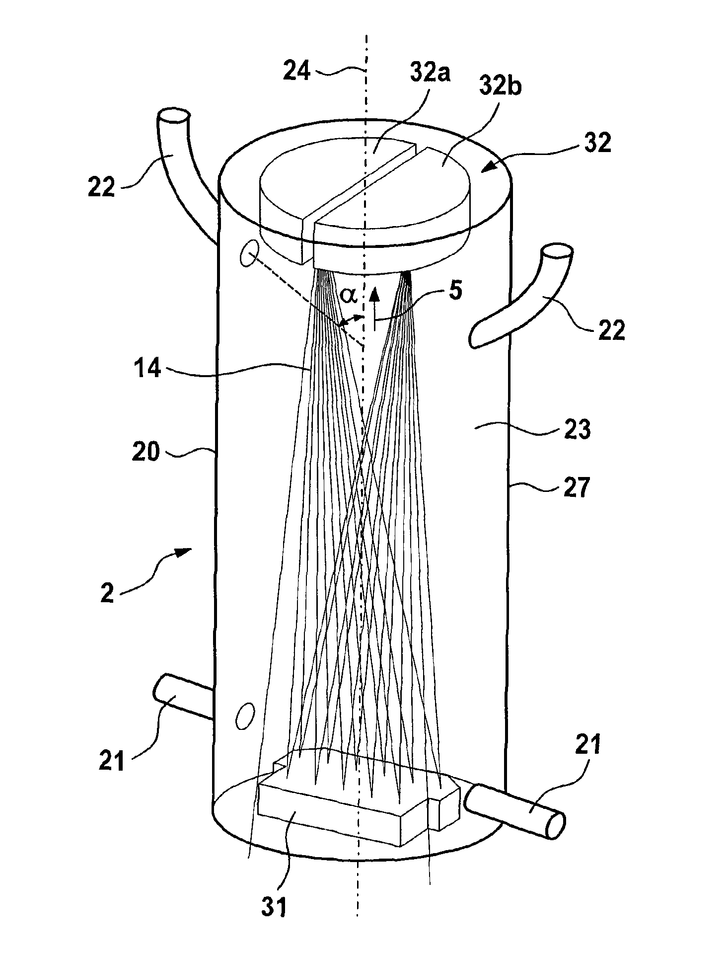
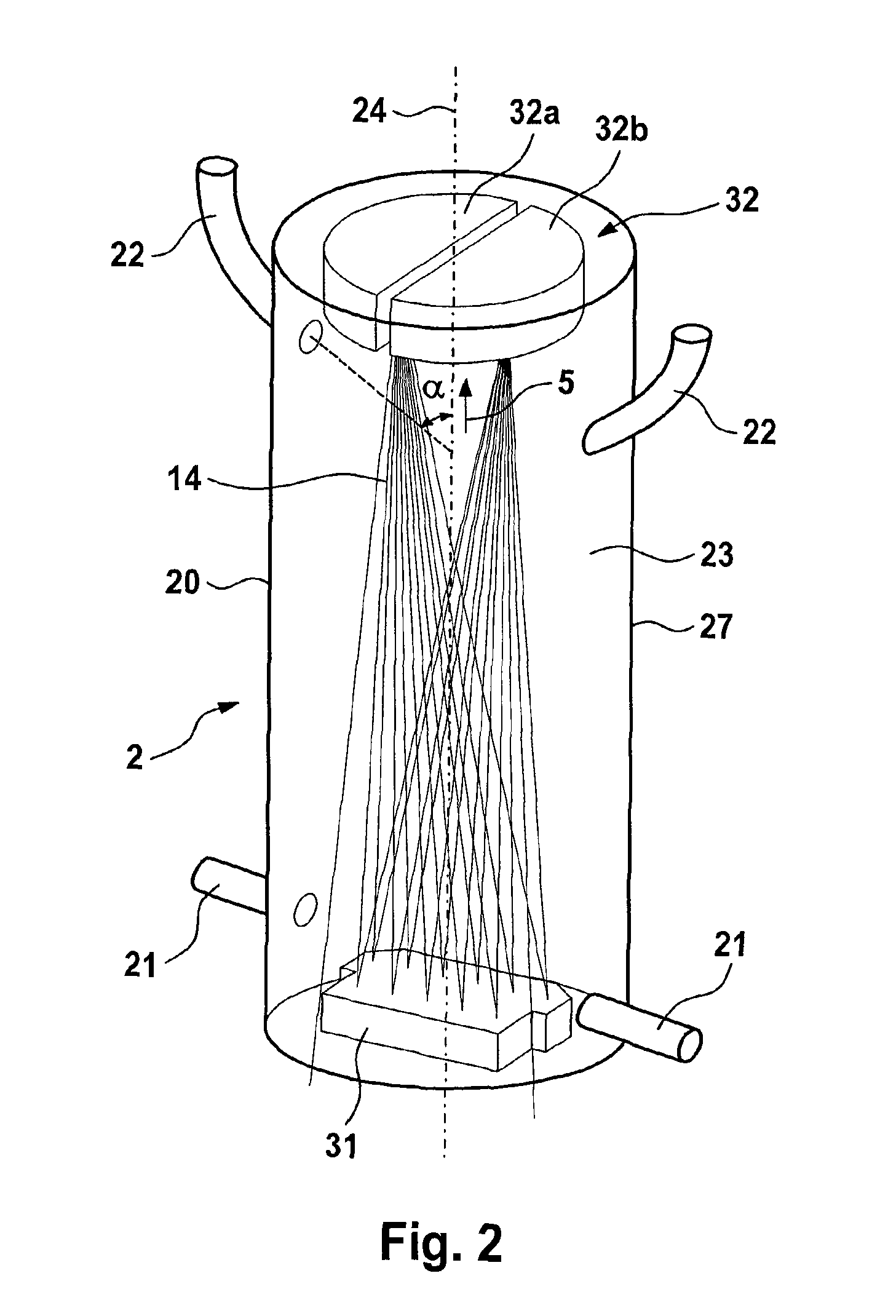
[0033]The gas cell 2 is the actual measuring cell...


PUM

PropertyMeasurementUnit
angleaaaaaaaaaa
diameteraaaaaaaaaa
lengthaaaaaaaaaa

Abstract

A measuring cell for a gas analysis spectrometer has an inner chamber for a sample gas to be analyzed and an inlet and an outlet which are connected thereto. A traversing optical path for a measuring beam is formed in the inner chamber. The measuring cell is tubular, the inlet and the outlet are arranged at opposite ends, and the inner chamber of the measuring cell has a cross-sectional shape that is monotonic over the length of the tube and which has an oval-shape at the start, which disappears toward the end. That special shape results in fast gas exchange and thus high dynamics, even with larger measuring cells, which have high sensitivity due to the long optical paths thereof. Two characteristics which until now appeared to be conflicting are thereby combined.

Description

[0001]This application is a continuation of Ser. No. 13 / 885,178, filed Jul. 18, 2013 as the national stage of PCT / EP2011 / 070462, filed on Nov. 18, 2011 and claims Paris convention from DE 10 2010 051 928.6, filed Nov. 19, 2010, the entire disclosures of which are hereby incorporated by reference.BACKGROUND OF THE INVENTION[0002]The invention concerns a measuring cell for a gas analysis spectrometer with an inner chamber for a gas to be analyzed, an inlet and an outlet, wherein a traversing optical path for a measuring beam is formed in the inner chamber.[0003]The optical analysis of gases is applied widely in various areas of technology. Special requirements are demanded by exhaust gas measurement applications for internal-combustion engines. Due to increasingly strict exhaust gas regulations, not only is a high level of sensitivity required to achieve a low detection threshold, but also a high time resolution to ensure a sufficiently good dynamic response of the measurement, in par...

Claims


Application Information

Patent Timeline
Patent Type & Authority Patents(United States)
IPC IPC(8): G01N1/10G01N21/11G01J3/02G01N21/03
CPCG01J3/0267G01J3/021G01N21/031G01N21/11G01N2201/02
Inventor KRAUSE, SVENWANG, YIFEISCHOMANN, LARSMATZ, GERHARDHARIG, ROLANDEICHMANN, JENS
Owner CHEVROU USA INC
Why Eureka
Try Eureka